Hall Effect vs potentimeter

Thread Starter

itolond

Joined Feb 27, 2010
23
Hi forum,

Am i on the Wrong track?

I am building a electric jeep for my son, all going ok but the throttle is a sticking point.

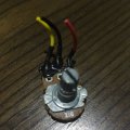
I have a 12-24v dimmer controller (http://ledlights4you.co.uk/mr16-12v-led-96w-dimmer-switch) which is ok at controlling the 12v DC motors, however i want to have the 'throttle' setup, rather than build i have obtained a hall effect throttle (http://www.aliexpress.com/item/New-...2283505814.html?spm=2114.13010608.0.98.fqwiFD).
I thought or think i can swap out the pot for the ll effect and still use the controller, correct, or what should I need to do here?

regards,

I
 

wayneh

Joined Sep 9, 2010
17,498
Can you find any more detailed information about it? It's impossible to tell from the information at that link.

If you already have the throttle, just measure the resistance to see if it's acting like a pot. Show us a picture of the connectors.
 

Techno Tronix

Joined Jan 10, 2015
139
Can you find any more detailed information about it? It's impossible to tell from the information at that link.

If you already have the throttle, just measure the resistance to see if it's acting like a pot. Show us a picture of the connectors.
I agree. More detailed and specific information can make you more clear.
Hall effect used in moving magnet creates changes in magnetic field strength that are detected by an electromagnetic sensor where potentiometer is a Variable resistor where an electrical contact moves across conductive plastic element.
 

Tonyr1084

Joined Sep 24, 2015
7,905
Without knowing HOW the throttle works I couldn't begin to guess. It would appear that the controller modulates the amount of power going to your motors (8 amps max), be it voltage or current - or PWM (Pulse Width Modulation). The throttle (pedal) - it MIGHT be some sort of PWM but all I can do is guess.

If you have both and have access to an oscilloscope then you can test each and see how their individual outputs work. Let us know what you find and then we can advise - that is if you don't end up figuring it out on your own.
 

AnalogKid

Joined Aug 1, 2013
11,056
"Working voltage 0-5 V" *implies* to me that the output varies from 0 V to 5 V depending on position, probably at a very low output current, so the motor controller needs to be able to take this as an input. If your controller expects the wiper of a pot with the endpoints tied to 0V and 5 V, then you're pretty close. Note the 17 unsupported assumptions in this post.

ak
 

Thread Starter

itolond

Joined Feb 27, 2010
23
Hi Forum members and thanks for the replies,

I thought i had notifications on - but apparently not :-(

I don't have access to an oscilloscope, and you are right there isn't much to go on from the urls. This is a throttle for my sons jeep (12v DC motors). I a not sure if wire colour has much bearing on this (the throttle is designed for a electric scooter - and these plug into a controller of sorts) but the throttle has 3 wires (Red,Green Black). from what i can gather you are spot on there should be a 5v supply to the throttle then depending on the position a wire (I think green) will have a variable voltage from 0-5v range.
I was hoping to be able to use this idea - but frankly I am somewhat lost on electronics beyond the above. Not sure what to do next really
 

Thread Starter

itolond

Joined Feb 27, 2010
23
Can you find any more detailed information about it? It's impossible to tell from the information at that link.

If you already have the throttle, just measure the resistance to see if it's acting like a pot. Show us a picture of the connectors.
how does one measure to see if its acting like a pot ?

The 12v dimmer has a 3 wire connector with a pot .....
 

Thread Starter

itolond

Joined Feb 27, 2010
23
found this information on the hall effect if it helps


  • Input Voltage: 5V
  • Output: 0.8-4.2V
  • Output Rated Load Current: 10ma
  • Output Type: Voltage
  • Pedal Rotation Angle: 15 Degrees
  • Max Load Current: 10ma
 
Top