Hall Effect switched Impulse Motor

Thread Starter

spark727

Joined Aug 22, 2017
2
Hi Friends,

i am new here....... and i would need some help of you electronics Guru's here.

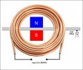
I want to drive a hall effect switched pulse motor, where i am able to use input voltage 9 - 300 VDC to the coil, and be able to switch to power on and off to the coil by a Hall Effect switch.

Does anyone has a schematic like this available?...... or can anyone help me make a schematic like that?
 

Attachments

wayneh

Joined Sep 9, 2010
17,496
You'll want a MOSFET to switch the power to the coil. You'll need a high voltage MOSFET rated to at least about 400VDC and 2X the coil current at 300VDC, which you haven't specified. It may need substantial heat-sinking as well but you won't know that until you know the coil current and the Rdson rating of the MOSFET, and its heat dissipation abilities.

You will need a snubber diode in parallel to your motor coil to absorb the inductive spike when the current is turned off. This will protect your MOSFET. I believe the diode needs to be rated to roughly double the coil current and at least double the voltage.

What you need to drive the MOSFET will depend a lot on the frequency, which is likely not "high". I mean it's probably more like 10kHz max and not over 100kHz. So I think you may not need a MOSFET driver IC, but it wouldn't hurt except for the extra complexity.

The driving signal can come from a comparator or Schmitt trigger. This will square up the signal from your sensor so that the signal going forward to the MOSFET (or driver IC) is fully digital, on or off, and nothing in between. I've never worked with a hall sensor signal can't say much more. I'd search around for hall sensor circuits to see how they handle this. It's ultimately a conversion of the analog sensor signal into a digital signal.

The part of this I'm fuzzy on is how you'll control your pulse timing. I mean, the precise time that your sensor's digitized output goes high or low may not be identical to when you want the current turned on or off. Being able to change the position of the sensor will help but there may be more to it than that. You might need two sensors so you can separate the "on" signal time from the "off" time.
 

Reloadron

Joined Jan 15, 2015
7,501
Do you want to switch the power on and off or do you want to reverse the power polarity?

I see wayneh already posted as I began to type. So for On/Off you would, as mentioned, use a MOSFET solution or an IGBT solution and for polarity reverse again a MOSFET circuit configured in an H-Bridge. High current and voltage you may want to look at IGBT designs.

Ron
 

Thread Starter

spark727

Joined Aug 22, 2017
2
Thank you Wayneh,
the current will no not higher than about 2 Amp........, yes the frequency will be low, as there is only one magnet...... my guess is, it will be somewhere around 4000 rpm, why i guess that, because i tried it naked, just to put the wires on the shaft as commutators , and with 260v it was 3470 rpm for a very short time before the wires melted down.

Thank you Ron..... but i think switching the power on and off is better than reverse polarity, i believe if we revers it, the coils will become very hot..??

i been searching around for a while, but couldn't find anything......... what is out there is mainly around 12 to 24v

You'll want a MOSFET to switch the power to the coil. You'll need a high voltage MOSFET rated to at least about 400VDC and 2X the coil current at 300VDC, which you haven't specified. It may need substantial heat-sinking as well but you won't know that until you know the coil current and the Rdson rating of the MOSFET, and its heat dissipation abilities.

You will need a snubber diode in parallel to your motor coil to absorb the inductive spike when the current is turned off. This will protect your MOSFET. I believe the diode needs to be rated to roughly double the coil current and at least double the voltage.

What you need to drive the MOSFET will depend a lot on the frequency, which is likely not "high". I mean it's probably more like 10kHz max and not over 100kHz. So I think you may not need a MOSFET driver IC, but it wouldn't hurt except for the extra complexity.

The driving signal can come from a comparator or Schmitt trigger. This will square up the signal from your sensor so that the signal going forward to the MOSFET (or driver IC) is fully digital, on or off, and nothing in between. I've never worked with a hall sensor signal can't say much more. I'd search around for hall sensor circuits to see how they handle this. It's ultimately a conversion of the analog sensor signal into a digital signal.

The part of this I'm fuzzy on is how you'll control your pulse timing. I mean, the precise time that your sensor's digitized output goes high or low may not be identical to when you want the current turned on or off. Being able to change the position of the sensor will help but there may be more to it than that. You might need two sensors so you can separate the "on" signal time from the "off" time.
Thank you Wayneh,
the current will no not higher than about 2 Amp........, yes the frequency will be low, as there is only one magnet...... my guess is, it will be somewhere around 4000 rpm, why i guess that, because i tried it naked, just to put the wires on the shaft as commutators , and with 260v it was 3470 rpm for a very short time before the wires melted down.

Freddie

Do you want to switch the power on and off or do you want to reverse the power polarity?

I see wayneh already posted as I began to type. So for On/Off you would, as mentioned, use a MOSFET solution or an IGBT solution and for polarity reverse again a MOSFET circuit configured in an H-Bridge. High current and voltage you may want to look at IGBT designs.

Ron

Thank you Ron..... but i think switching the power on and off is better than reverse polarity, i believe if we revers it, the coils will become very hot..??

Freddie
 
Last edited by a moderator:
Top