 Facebook
 Google
 GitHub
 Linkedin
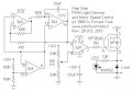
My Hall effect slide pot throttle works very well. I built the Forrest Cook PWM circuit and mated them. (both diagrams attached for reference)
My diagram shows the comparator stage and my output section with brake FET and its adjustment control.
My question is why does it blow the source FETs when I use a high current motor? No issue with a low current motor. The high current motor pulls about 3 amps at 3 volts free running no load during brush break in. How many more amps would it pull under heavy load at 13V? it is fused at 30 amps and has not blown a fuse. I do not know exactly how much current the big motor pulls.
Does the circuit look reliable? Any obvious improvements? (I am stuck with the high side layout. The motor is grounded That cannot change)
Attachments
-
310.9 KB Views: 22
-
 51.6 KB Views: 18


