Facebook
 Google
 GitHub
 Linkedin
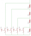
I am trying to create a potientiameter (like a slide pot) from a string of hall effect switches (open collector outputs). I have it fabricated as a series of resistors tapped into by the open collectors. So the ground point moves along the string of resistors. The equivelent circuit is a linear pot BUT the wiper is ground. You can reference either end of the string but thats it.
Using it as the bottom of a voltage divider does not yeild a linear result.
What sort of circuit (op amp or otherwise) will allow it to source linear voltage like a pot?
Donald
new to hobby electronics
Using it as the bottom of a voltage divider does not yeild a linear result.
What sort of circuit (op amp or otherwise) will allow it to source linear voltage like a pot?
Donald
new to hobby electronics