Hall Effect Pulse Train Circuit Modification

Thread Starter

asterof

Joined Jan 8, 2025
6
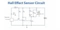
Flow Hall Effect Pulse Train
I have a circuit that will energize a relay if hall effect is true
or hall effect pulses are fast. As long as pulse rate is high relay stays energized
However if flow stops and hall effect lands high relay will stay true
Any ideas on what modification I would need to make, so if pulsing stops and hall effect is true
relay will drop out.
 

Attachments

crutschow

Joined Mar 14, 2008
38,323
if hall effect is true or hall effect pulses are fast. As long as pulse rate is high relay stays energized
However if flow stops and hall effect lands high relay will stay true
Any ideas on what modification I would need to make, so if pulsing stops and hall effect is true
relay will drop out.
You could capacitively couple the output from the Hall Effect sensor, so it only responds to pulses.
How fast is "fast", and how slow before you want the relay to drop out?

LTspice sim of example circuit below:

1736352323332.png
 

crutschow

Joined Mar 14, 2008
38,323
when pulses are below 3PPS relay off and number of pulses above 3PPS relay on constand pluse meaning hall effect in high for more that 1 sec relay off
Okay.
Below is the sim of the first and second circuit stage modified to do that:

The output to Q2's base (red trace) goes low (relay off) about 1 second after the pulses stop low or high.

1736360175585.png
 

Thread Starter

asterof

Joined Jan 8, 2025
6
Im sorry I am not really understanding what you are saying. Are you saying take the output of my circuit and apply it to the 4n25 ? If so where does the relay go Q2b ?
 

Attachments

crutschow

Joined Mar 14, 2008
38,323
Im sorry I am not really understanding what you are saying. Are you saying take the output of my circuit and apply it to the 4n25 ? If so where does the relay go Q2b ?
No, sorry I didn't make it more clear.
U1 and Q1 are just to simulate your part of the circuit.
You add C1, C2, D1, D1, and R2 between your opto output and your Q2's input.
 

sghioto

Joined Dec 31, 2017
8,633
You add C1, C2, D1, D1, and R2 between your opto output and your Q2's input.
I breadboarded that circuit and the relay is always ON regardless if there is a High or Low pulse.
This circuit works but relay stays on until flow rate is zero.
Cap values can be changed to activate the relay above 3pps but then the relay will pulse below 3pps until flow rate is zero.
1736363287698.png
 

Thread Starter

asterof

Joined Jan 8, 2025
6
I breadboarded that circuit and the relay is always ON regardless if there is a High or Low pulse.
This circuit works but relay stays on until flow rate is zero.
Cap values can be changed to activate the relay above 3pps but then the relay will pulse below 3pps until flow rate is zero.
View attachment 339898
On my circuit which is on a PCB the relay will toggle as the hall sensor is triggered it follows the led. Not sure why your breadboard would energize the relay all the time, NM i read that wrong your new circuit stays on :)
 
Last edited:

kaindub

Joined Oct 28, 2019
176
Lets go old school
Use a 555 IC in monostable mode (I think)
Set the time period to be greater than the minimum interval between pulses
 

AnalogKid

Joined Aug 1, 2013
12,047
Basically, this is the same as a fan tach alarm circuit, one that takes tach pulses from a fan and produces an alarm signal when the fan speed drops below a setpoint. The classic circuit uses the two comparators in an LM393. This was published in the apps section of fan catalogs in the 70's and 80's.

As partly shown above, the secret to having the circuit produce an alarm if the sensor freezes either high or low is to have pull-up resistors on both ends of the input coupling capacitor. That is missing in schematic #1, but shown in #3 and #7. #2, #10, and #14 rely on a transistor's base current to discharge the coupling cap, making that current part of the detection window math. Better to separate the two functions.

Here is an old schematic that covers the idea. This is a slice from a larger schematic with four circuits. Pins 4 and 11 go off to a Vcc/2 reference voltage.

Buckeye game coming up. More later.

ak

FanFail-1-c.gif
 
Last edited:
Top