Facebook
 Google
 GitHub
 Linkedin

Hi there,
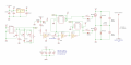
I am currently working on a half bridge solid state tesla coil. I have built a class e sstc but I am having trouble with this one. Things seem to be going wrong at the gate pin of my mosfets for the half bridge. Lots of heat on mosfets and no spark at output. At the moment, I have a signal generator attached to the feedback antenna to give a 606kHz (~resonant frequency of the secondary coil + topload) signal.
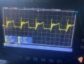
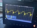
Lots of ringing at MOSFET gate. I originally had 6.8ohm resistors, but I replaced them with higher value to suppress ringing but not much changed.
Also Faze lead should be phase lead. Idk what I was thinking
I am currently working on a half bridge solid state tesla coil. I have built a class e sstc but I am having trouble with this one. Things seem to be going wrong at the gate pin of my mosfets for the half bridge. Lots of heat on mosfets and no spark at output. At the moment, I have a signal generator attached to the feedback antenna to give a 606kHz (~resonant frequency of the secondary coil + topload) signal.
Lots of ringing at MOSFET gate. I originally had 6.8ohm resistors, but I replaced them with higher value to suppress ringing but not much changed.
Also Faze lead should be phase lead. Idk what I was thinking
Attachments
-
 590.9 KB Views: 18
 -
 67.2 KB Views: 18
 -
 69.1 KB Views: 10
 -
 70.1 KB Views: 9