Gyrator for inductance measurement.

steveb

Joined Jul 3, 2008
2,436
Good that you noticed about the feedback. Even A1A has some positive feedback, as do they all, so it's a matter of the balance of negative and positive feedback, as you said.
Please overlook my earlier stupidity. I know what you mean by positive feedback. I was leaving work quickly and not thinking before. Basically, I'm trying to use the major positive feedback from the opamp orientation as a way to classify the circuits. Obviously, once you consider the frequency dependence of the opamp and with certain choices of the impedances, you can always find frequencies with positive feedback in certain cases.

I'm trying to see if I can post my results in a way that makes sense. I basically am trying to show that most of those circuits are difficult to stabilize under the most typical conditions. It's basically a claim I make with some trepidation and uncertainty. But, hey we're trying to learn, so don't shoot me if I'm wrong :)
 

steveb

Joined Jul 3, 2008
2,436
I posted an analysis for 4 of the 24 GIC circuits. (A1A A1B A1C and A1D)

It's definitely hard to read and follow, but my time is limited. I basically use the simple single pole model for an opamp and derive the effective impedance. At the bottom of the third page, there is an expression for the impedance. One could substitute the impedance values and the opamp gain into this formula and then enter into Matlab to get the bode plot and find out if it's stable. The formula uses the alpha coefficients to control the sign of the OPAMP feedback. Each of the two alpha values can be either +1 or -1.

In order to take this a little further, I derived a simplified expression under some assumptions. Under these assumptions it seems that stability is not possible unless both alpha values are equal to +1.

Thus, circuit A1A would seem to be the most useful of the 4 considered. I suspect a similar trend if the other circuits are similarly analyzed. So I would expect the following circuits to be the most useful.

A1A, A2D, A3A, B1A, B2D and B3A.

This is just a preliminary conclusion, so feel free to poke holes in it. I've been trying to visualize what conditions might make those other circuits stable, but I've been unable to find any conditions, and I wonder if the effects of the positive feedback from the orientation of the opamps is just too much to overcome.

The easiest way to disprove my statement is to find one set of conditions that results in a stable circuit. A spice simulation could easily show this. A real working circuit would be even more convincing.
 

Attachments

Last edited:
Excellent! I can't look at your work in detail until later today.

In the meantime can you tell me how your reasoning went in deciding that A2D was more likely to be useful than, for example, A2A?
 

steveb

Joined Jul 3, 2008
2,436
Excellent! I can't look at your work in detail until later today.

In the meantime can you tell me how your reasoning went in deciding that A2D was more likely to be useful than, for example, A2A?
Yes. First, I have to stress that I'm making conclusions prematurely, so just take these as educated guesses that aren't fully proven. I have not tried to analyze any of the other 20 circuits in great detail. However, the ones I mentioned seem to be the ones that have the opamp feedback arranged similar to A1A. (Hopefully, I identified them correctly - I just did it by looking and could have made a mistake)

Anyway, my guess is that those topologies are easier to work with since they should have transfer functions that are easier to stabilize with component choice. Of course, unless/until we look at the actual equations for those circuits, I can't say much more than that. In the case of A1B, A1C and A1D, I have been unable to find typical conditions that result in stability. I could have made a mistake, but that would be easy to prove with a spice simulation, or maybe the OP (Bill) can test since he is building a circuit anyway.

There is quite of bit of work needed to be rigorous, so my feeling is that we can make faster progress if I'm bold and state things without fear of being wrong. If I had more time, I would use Matlab, Spice and experiments to verify. I'm happy to be proved wrong here, since I will learn something.
 

steveb

Joined Jul 3, 2008
2,436
Excellent! I can't look at your work in detail until later today.

In the meantime can you tell me how your reasoning went in deciding that A2D was more likely to be useful than, for example, A2A?
OK, I suspected you were asking this because you thought I made a mistake, so I went back and checked, and it looks like I did. I had done a quick look by eye, but judged wrong. I wrote out quick signal flowgraphs for each topology to identify the configuration that looks most stable based on the absence of primary positive feedback paths. They are as follows.

A1A, A2B, A3A, B1A, B2B and B3A

These are still preliminary conclusions, but now are based on a quick analysis. It's still possible that some of the other arrangements can be stabilized, but my gut feeling is that these 6 circuits are more useful.

Have you ever considered a career in psychology? ;)
 
Sorry to be so long getting back; I've been gone for a few days.

Your analysis looks good up to the bottom of page 3. I haven't checked to see if your later approximations are of negligible effect.

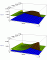
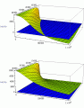
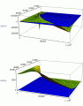
Here's some of what I've done. This image shows the real part of the impedance at node 1 (your designation is V1) with a capacitor at position Y2 and Y4. The top image is with the cap at Y2, the bottom one with the cap at Y4. This is a 3D plot with the opamp gain bandwidth varying from 0 to 1,000,000 and the frequency of the impedance calculation varying from 0 to 40,000. What I've plotted is the real part of the impedance with a blue plane to represent zero. Parts of the plot above the plane are positive and parts below the plane are negative.

The first image shows the results for the A2A topology; note that the real part of the impedance never goes negative.

The second image is the result with the A2D topology. When the capacitor is in the Y2 position, the real part of the impedance is sometimes negative, but when the cap is in the Y4 position, it is always positive.

The third image is the result with the A1C topology. As with A2D, the circuit has an input impedance with a negative real part if the cap is in the Y2 position.

The A1B and A1D topologies have non-negative real parts in this circuit, but they are apparently not DC stable. If simulated, they either oscillate in a kind of relaxation mode or they latch up.

According to Bruton, the A1A topology is unconditionally stable, but A2A may be unstable for certain component and opamp gain values.

B2D, the topology in an earlier thread:
http://forum.allaboutcircuits.com/showthread.php?t=15751

is only AC stable for the capacitor in the Y4 position.
 

Attachments

OK, I suspected you were asking this because you thought I made a mistake, so I went back and checked, and it looks like I did. I had done a quick look by eye, but judged wrong. I wrote out quick signal flowgraphs for each topology to identify the configuration that looks most stable based on the absence of primary positive feedback paths. They are as follows.

A1A, A2B, A3A, B1A, B2B and B3A

These are still preliminary conclusions, but now are based on a quick analysis. It's still possible that some of the other arrangements can be stabilized, but my gut feeling is that these 6 circuits are more useful.

Have you ever considered a career in psychology? ;)
Actually, I wasn't thinking you had made a mistake. I was just wondering how you weighed the various connections to the opamp + and - inputs in deciding whether the overall feedback was positive or negative.

I tried to figure that out when I first was considering these 24 topologies, but after analyzing a few, I decided that you just can't tell for most of them without carrying out an analysis.
 

steveb

Joined Jul 3, 2008
2,436
I tried to figure that out when I first was considering these 24 topologies, but after analyzing a few, I decided that you just can't tell for most of them without carrying out an analysis.
Yes, I see that now. I thought I could visualize the direction of the feedbacks, but my mistakes show this is difficult. There are several feedback paths, and it's hard to see them all just by looking. The ones I mentioned have all negative primary feedback paths, but the feedback is significantly different in each case. So, I can see your previous point of asking which might be better, and under which conditions.

I'm curious if you think the other circuits are too difficult to work with, or if there are cases that might be useful. With my limited time, I'm tempted to just study those 6 circuits. Still, I'm curious if some of those other circuits can be stabilized.

I scanned through a few OPAMP circuit books find that circuit A1A is the one I see most often, and this is the one I studied back in school. I don't know if that means anything.

I'll look through the results you posted. Looks interesting!
 

steveb

Joined Jul 3, 2008
2,436
Sorry to be so long getting back; I've been gone for a few days.

Your analysis looks good up to the bottom of page 3. I haven't checked to see if your later approximations are of negligible effect.

Here's some of what I've done.....
These are interesting graphs. I decided to first look at the results for the A1A, A1B, A1C and A1D circuits since this is work we have both done and we can make comparisons.

We seem to be in agreement that A1A is unconditionally stable; and that both A1B and A1D are unstable.

This leaves A1C which you have those nice 3D plots in the 3'd figure. However, I'm trying to figure out how to interpret stability from these plots. Is there a trick to determine stability directly from the real part of the impedance value. Since we are simulating an inductor, I would expect the real part of impedance to be near zero when gain is high and frequency is low. It looks like this happens with a capacitor at either Y2 or Y4. But, how do you know if it's stable under those conditions? I generally determine stability based on whether poles are in the right half plane. How do you determine that from the plots?
 
Is there a trick to determine stability directly from the real part of the impedance value. Since we are simulating an inductor, I would expect the real part of impedance to be near zero when gain is high and frequency is low. It looks like this happens with a capacitor at either Y2 or Y4. But, how do you know if it's stable under those conditions? I generally determine stability based on whether poles are in the right half plane. How do you determine that from the plots?
Think about a circuit consisting of a resistor, a capacitor and an inductor, all in series. Let the capacitor have an initial charge, and then close the loop with all three in series. There will result a decaying oscillatory current. The energy lost in the resistor is responsible for the decay of the current.

If the resistor is a negative resistor, the oscillatory current will grow (without bound, if the components are ideal). This is unstable behavior, and the impedance has roots in the right half plane if the resistor is negative.

So, an impedance having a negative real part is potentially unstable. I say potentially, because you can probably connect a real, positive, resistor in such a way as to make the total circuit losses positive, restoring stability.

And, that, by the way, is why some 2 terminal impedances may be short circuit stable but not open circuit stable, and vice versa.

The reason for considering more than just the A1A topology, is that some of the others are less sensitive to GBW variations on the opamps, but some of the ones with least GBW sensitivity are also unstable. Darn!!

Just for grins, make all the admittances in the A1A circuit 10k resistors. Leave node 1 open, and calculate the resistance at node 3 with various opamp gains, such as 1, 10, 100, 1000, 10000.
 

steveb

Joined Jul 3, 2008
2,436
If the resistor is a negative resistor, the oscillatory current will grow (without bound, if the components are ideal). This is unstable behavior, and the impedance has roots in the right half plane if the resistor is negative.
Ah, OK I think I understand. You are saying that the circuit is stable by itself, but the cases where the real part of the impedance is negative can result in instability once used in the application.

The 3D plots you showed. How is the data generated? Is it from Spice simulation?

So what I need to do is take my previous analysis and study the A1C case with a capacitor at Y2 or Y4. I'll do that, and then report back.
 
Ah, OK I think I understand. You are saying that the circuit is stable by itself, but the cases where the real part of the impedance is negative can result in instability once used in the application.
And sometimes a circuit may oscillate standalone if the negative resistance (and associated inductance) exists at a high enough frequency. The calculated behavior of a circuit at AC may be different from its behavior at DC. A standalone circuit may just latch up if there is sufficient positive feedback, driving the opamp outputs to the rail. Some of the topologies out of the 24 do this, even though AC analysis would seem to indicate that they would correctly generate a negative inductance. Determining by analysis if a circuit will have this DC instability is a difficult problem, only recently (mostly) solved. In the past, it was thought that if any node in a circuit exhibited negative differential resistance, instability was indicated. Recent papers in the IEEE journals suggest that it's not that easy to determine.

For example, make all the resistors 10k and calculate the resistance at node 3 in the A1A topology.

The 3D plots you showed. How is the data generated? Is it from Spice simulation?

So what I need to do is take my previous analysis and study the A1C case with a capacitor at Y2 or Y4. I'll do that, and then report back.
I took the calculated driving point impedance function, equivalent to what you have on the last page of your analysis, substituted real numbers for the impedances, and plotted the real part of the impedance with a computer algebra system.

The two opamps were assumed identical, without a single pole roll off, and a gain of 100,000. If I were going to use this circuit in a real application, I would also check with non-identical opamps, because I've noticed some of the topologies exhibit a negative resistance with non-identical opamps, but not with identical opamps.

The numbers I used are Z1=7870, Z2=10k, Z3=10k, Z4=10k, Z5=8060 with either Z2 or Z4 replaced with a 1 nF capacitor for the two plots. These numbers were selected because they were used in a 2nd order bandpass filter I found on the internet.

I haven't checked to see if any simplifying assumptions you made in deriving your final expression will have a noticeable effect on the result. You might want to watch out for that.
 

steveb

Joined Jul 3, 2008
2,436
I took the calculated driving point impedance function, equivalent to what you have on the last page of your analysis, substituted real numbers for the impedances, and plotted the real part of the impedance with a computer algebra system.
I've been a little busy and couldn't get to this problem. However, tonight I had a few minutes and tried a special case of circuit A1C with a capacitor in place of Z4 and resistors for Z1, Z2, Z3 and Z5. This case was a little easier to calculate than putting a capacitor for Z2. I was able to get a transfer function with a 3rd order polynomial (in s) in both the numerator and denominator. I made one simplifying assumption that the low frequency open loop gain is large which is true for any practical OPAMP. With the transfer function in this form it is straightforward to determine stability by looking at the sign of the coefficients of the polynomial in the denominator. They either have to all be positive or all negative, in order for the circuit to be stable. If they are not, then there is at least one pole in the right half plane. The form of the coefficients makes it clear that only circuit A1A can be stable with those constraints.

I think this gets missed when you just plot the real part of impedance. Now, this analysis is just for the circuit by itself. I have not analyzed this when used as an RLC series circuit. It is quite possible that if you hook the circuit into an RLC circuit, the stability is restored. However, one thing seems clear: using circuits A1B, A1C and A1D is not for the faint of heart. While circuit A1A is relatively easy to use.
 
Last edited:

Thread Starter

Wendy

Joined Mar 24, 2008
23,816
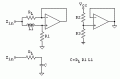
I'm thinking of building this unit using low quality op amps. I figure the DVM uses low level low frequency signals to do the test, the worst that will happen is it won't work.

I'm not sure how to judge the calibration short of using a better LCR meter and transfering the calibration standard.


RL = 1Ω, R1 = 100Ω, R2,3 = 1 KΩ

What do you think, does it have a chance of working?
 

Attachments

Last edited:
Some low cost DVMs measure capacitance by applying the capacitor to what amounts to a relaxation oscillator, and measuring the frequency. You should try looking at the voltage across a cap while your DVM is measuring it, and see if the voltage is a triangle or saw tooth wave, or if it's a sine wave.

The gyrator scheme may now work as well if the waveform is a sawtooth.
 
Top