Facebook
 Google
 GitHub
 Linkedin
Hey everyone I play the electric guitar and am seeking advice for my volume pot, getting straight to the point, guitars for the most part use passive circuitry to alter voltage created from magnetic pickups, a major part of this circuitry is the volume potentiometer which controls the signal output of the pickups on their way to the amp.
What is common practice in the guitar world is to run our amps to sound distorted to rock out and then we clean up the amps sound with our guitars volume control in order to play lighter chords/strumming etc, (and not have to run back to adjust the amp live)
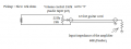
A big problem however is the guitars potentiometers alter the signal and tone coming from the guitar, removing high frequencies and creating a muddy undesirable sound the more we "clean up" our tone, they have invented "fixes" such as a treble bleed capacitor which is placed across the volume pot's input/output lungs and bleeds high frequencies into the signal when the volume pot is turned down in order to compensate, however this only captures minimal frequencies and although better than a standard pot, many including myself say it does sound thin at times.
Therefore I have come here to try and work out a way to have my guitar volume control retain it's frequency response through it's turn in order to have a cleaned up amp and the same full frequency response of a wide open potentiometer, some have said a buffered circuit could fix the issue but this would mean placing a 9v battery onboard, which is undesirable yet may be the only option.
I am by no means an electrical engineer, I can do basic soldering and can barely read electrical diagrams, can you help me?
What is common practice in the guitar world is to run our amps to sound distorted to rock out and then we clean up the amps sound with our guitars volume control in order to play lighter chords/strumming etc, (and not have to run back to adjust the amp live)
A big problem however is the guitars potentiometers alter the signal and tone coming from the guitar, removing high frequencies and creating a muddy undesirable sound the more we "clean up" our tone, they have invented "fixes" such as a treble bleed capacitor which is placed across the volume pot's input/output lungs and bleeds high frequencies into the signal when the volume pot is turned down in order to compensate, however this only captures minimal frequencies and although better than a standard pot, many including myself say it does sound thin at times.
Therefore I have come here to try and work out a way to have my guitar volume control retain it's frequency response through it's turn in order to have a cleaned up amp and the same full frequency response of a wide open potentiometer, some have said a buffered circuit could fix the issue but this would mean placing a 9v battery onboard, which is undesirable yet may be the only option.
I am by no means an electrical engineer, I can do basic soldering and can barely read electrical diagrams, can you help me?