Facebook
 Google
 GitHub
 Linkedin
Hello everyone.
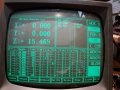
I need to feed to an GT65 Amstrad monitor, a video signal from an hercoules type video card. The video signal has a 18.432Khz horizontal synchronization frequency, and 50Hz vertical.
I managed to synchronize the picture, horizontal by changing the inductance of the L703 coil, and vertical, but the problem is that the picture is not centered on CRT, horizontal. I try to adjust the frame via the magnets on the back of the neck, but it did not bring much. I think by changing some components on the pcb of the monitor will fix the problem, but i don't know which? Any help will be appreciated. Attached is the electronic schematic of the monitor, and a picture showing the problem.
Attachments
-
174.5 KB Views: 8
-
 207.9 KB Views: 13