 Facebook
 Google
 GitHub
 Linkedin
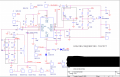
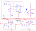
We have designed a custom board using the MABC_001_DP000L. We are Using this custom board to provide Biasing voltages to the QPA1022 Amplifier.
We tested the custom board with the following set-ups:-
SETUP-1:- WITH NO LOAD(Power amplifier)
Under this setup Gate voltage is being generated and can be varied by varying VR1(10K pot). VDS is being generated and controlled by TTL input.
SETUP-2:- WITH LOAD(Power amplifier)
Under this setup, the Gate voltage is being dropped to -1.5V, because of this we are unable to set the Drain current but the Drain voltage is being generated.
For the reference find the SETUP-1, SETUP-2 and schematic snapshots..
Can Somebody help in debugging this ?
Thanks In advance
Attachments
-
 68.5 KB Views: 12
 -
 28.1 KB Views: 12
 -
 477.2 KB Views: 12
 -
 374.9 KB Views: 11


