GaN FET Driver Circuit

Status
Not open for further replies.

Thread Starter

JulesP

Joined Dec 7, 2018
383
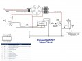
For my CEMF pulse generator, I have come up with an upgraded design for a replacement trigger and drive circuit using a GAN FET and associated driver. My IRF840 was getting fairly hot and, as I've heard these new GaN-based FETs are very robust, that I would give it a try. Also, the proposed use of a driver chip is to reduce the shut-off time of the FET thereby increasing the voltage transient at the Drain.

The present circuit and the proposed one are shown in the attached images.

I have several queries about using the Driver and am not fully confident on whether I have all the pins I need connected, with the FET serving as a low-sided switch?

Firstly, I'm not sure if I need pins 5,10 & 16 connected in some way (chip pinout data is on the image). Also, I'm querying if I can use the same Hall sensor setup, with the BC5409, as a signal to feed the STDRIVEG600 chip? And what might the resistance be just before the Ferrite bead?

The use of the Ferrit bead and the DC-Link snubber (whatever that is) are both recommended in the spec notes for the GAN FET.

Thank you.
 

Attachments

Last edited:

MrSalts

Joined Apr 2, 2020
2,767
A few questions about your original design....
A) Your NPN BC549C is inverting the signal of your sensor signal, right? That is, when the sensor wire is high, you want the Mosfet to be off? If that is not true, you'll need to connect things a bit differently (I.e. connect sensor wire directly to the Mosfet (through a small value resistor) if the sensor wire voltage goes from 0 to 10+ volts to turn the Mosfet off or on (without giving any voltages in between).

B) does your sensor wire give only an on or off voltage or all voltages in between? What voltage range?

C) right now, your Mosfet gate sees 7.5v when the sensor wire is 12VDC (if it ever gets that high). Look at the resistor network that is dividing the sensor wire voltage. It doesn't really make sense to me. You should have 10v on the Mosfet gat (specifically that IRF840 gate. It is only specified at 10v. Change the resistor from gate to ground to a 10k and check if you get better results.

D) this IRF has fairly high on-resistance (0.8 ohms) and will get hot with some amps through it. There are many better choices for 12VDC supplies with on resistance in the single-digit milliohms (or fractions of a milliohm). These modern mosfets can handle 10s of amps without much heating and without the complexity you are creating for the GaNFET.


https://assets.nexperia.com/documents/data-sheet/PHP191NQ06LT.pdf
 
Last edited:

Thread Starter

JulesP

Joined Dec 7, 2018
383
A few questions about your original design....
A) Your NPN BC549C is inverting the signal of your sensor signal, right? That is, when the sensor wire is high, you want the Mosfet to be off? If that is not true, you'll need to connect things a bit differently (I.e. connect sensor wire directly to the Mosfet (through a small value resistor) if the sensor wire voltage goes from 0 to 10+ volts to turn the Mosfet off or on (without giving any voltages in between).

B) does your sensor wire give only an on or off voltage or all voltages in between? What voltage range?

C) right now, your Mosfet gate sees 7.5v when the sensor wire is 12VDC (if it ever gets that high). Look at the resistor network that is dividing the sensor wire voltage. It doesn't really make sense to me. You should have 10v on the Mosfet gat (specifically that IRF840 gate. It is only specified at 10v. Change the resistor from gate to ground to a 10k and check if you get better results.

D) this IRF has fairly high on-resistance (0.8 ohms) and will get hot with some amps through it. There are many better choices for 12VDC supplies with on resistance in the single-digit milliohms (or fractions of a milliohm). These modern mosfets can handle 10s of amps without much heating and without the complexity you are creating for the GaNFET.


https://assets.nexperia.com/documents/data-sheet/PHP191NQ06LT.pdf
I see what you’re saying about the sensor but it works and all the coils are activated when one of the rotating magnets approaches it since the Hall signal goes low when the Mag field is detected.

I will have to try some measurements to see if there is a range of voltages coming from the sensor. Will get back on that on Monday.

Similarly I will measure the FET gate voltage and see what’s happening. The 1k resistor there is presumably dropping the volts where it shouldn’t.

While FET heating is one issue, and I’m sure there are fets that have a much lower on resistance, my reason for using a drive is to reduce the shut-off time as explained.

If a GaN and Driver is overkill then can you suggest a FET and driver that would be better suited to my needs?
 

Thread Starter

JulesP

Joined Dec 7, 2018
383
I hoped the generator flipped down to be powered by his bicycle's tire.

Have you noticed one of the topics that this form covers in ‘energy harvesting’. If you don’t intend to be helpful I will report it and go elsewhere
 

Thread Starter

JulesP

Joined Dec 7, 2018
383
hi Jules,
Is this an Over Unity device.?
ie: gives equal or more power out, than the power input.

Moderation
No, it’s experimenting with energy harvesting which is the basis of every alternative energy system on the planet. You get more energy out than WE put in so it has a CoP (Coefficient of Performance) greater than one, just as every air and ground source heat pump for example. There are people of this site who seem to be ignorant of these facts and think this all means energy is being created from nowhere (contra to 1st Law of thermodynamics). Sure there are some lay people in the world who believe that is possible but as a fully trained scientist (retired) I know otherwise. A few people on this site like to confuse me with such people and I never use such terms. Devices with a CoP>1 are all around us and I’m exploring some properties of HV transients and electrostatics. It’s a shame that some like to dump their angst on me instead of where it belongs. I have had some great help over the last three years from forum members but I have just about had enough of the purile schoolboy attitude of a few ignorant ones who aren’t educated enough to distinguish fact from fiction. Here endeth my rant.
 

Thread Starter

JulesP

Joined Dec 7, 2018
383
And to add a suggestion: that people educate themselves on the difference between ‘efficiency’ and CoP. No system can be more than 100% efficient (BY DEFINITION) but many systems have a CoP>1. A lot of people confuse these and while some in the world think you can have efficiency >100%, most with any nouse will know that you can’t but that you can have a CoP>1. Just look around
 

Thread Starter

JulesP

Joined Dec 7, 2018
383
Oh, well you should have said so. That is completely different than over unity.

per wikipedia..
Less work is required to move heat than for conversion into heat, and because of this, heat pumps, air conditioners and refrigeration systems can have a coefficient of performance greater than one.

So, which type of heat (energy) are you pumping/harvesting rather than simply converting from another type of energy? I didn't see the pumping/harvesting of cold or warm or antenna to collect electromagnetic signals in your circuit.
I didn’t expect that I had to spell it out. This site is supposed to focus on the circuits and not their application.
My motor/generator has a measured efficiency of 58% and a CoP of 1.16. I’m trying to improve it with some upgrades.

As a research topic that is not in the mainstream, I can’t tell you where the extra energy comes from although I have some good ideas that I won’t share on a forum. We say it comes from the ‘environment’ but there are some interesting properties and behaviours of high voltage spikes and in the best traditions of science, and having spent my professional life as a radiation physicist and then a science teacher, one gets data and evidence first before trying to explain the observations. I’ll let others squabble about the physics, meanwhile I want to operate a lot more lights than I have been using the available energy in the ‘environment’.
 

Thread Starter

JulesP

Joined Dec 7, 2018
383
I think you'll soon find you are right - this is not the place for this debate.
No problem. With all the existential crises facing humanity, human nature still doesn’t change and when confronted with something not understood or off the beaten track, it is attacked and ridiculed instead of embraced and explored.

It’s time I moved to a forum that at least gives the impression that it’s not fixed and can stretch its collective mind. So to all those here who have been a great help over the past three years, and to quote Douglas Adams, “Goodbye and thanks for all the fish”.
 

Thread Starter

JulesP

Joined Dec 7, 2018
383
Don't let one idiot push you away.
Perhaps you can post over-unity coefficient of Performance energy harvesting with unknown heat flows in/out on a site like this...
https://www.energyscienceforum.com/...2992-new-pulsed-dc-research-project#post73173
I have but they don’t have certain skills that electronics people do. As for the scientific method the attached will show that there are two primary methods and not one. Work that I’m doing is the Inductive one.
 

Attachments

Status
Not open for further replies.
Top