BLDC driver circuit using the IR2136s and the STP80NF06 MOSFETS

Thread Starter

gabcor38

Joined Nov 4, 2025
5
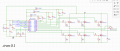
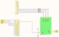
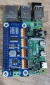
I have an assignment to build a BLDC driver circuit to power a motor. The professor told us we could do it any way we want and use any materials we can get our hands on. I am using the IR2136s and the STP80NF06 MOSFETS. the professor wants us to use a raspberry pi 4 and a Servo HAT (PCA9685) to send the PWM signals from the raspberry pi to the 6 input signals of the gate driver. I am using a 12 V power supply to power the whole thing. I will include the pictures of all the things done so far so you can have a look. I connect everything and run the program but the motor doesnt move. Im not sure what the problem might be but if anyone can help that would be really nice.
 

Attachments

Irving

Joined Jan 30, 2016
4,996
If the schematic in the 3rd pic is representative of your BLDC board then the problem could be that VS1/VS2/VS3 are not connected to the source/drain junction of each half-bridge:

bldc_fix.png
 

Thread Starter

gabcor38

Joined Nov 4, 2025
5
Thanks for your suggestions. I will check the HIN and LIN inputs. I think I messed up there. I will update you after. Thanks.
 

Thread Starter

gabcor38

Joined Nov 4, 2025
5
I made the corrections in my wiring and it seems to want to work. Neverthless, when I turn eveyrthing on and run the program it makes a humming sound. I dont know if it might be as a result of the PCA frequency or something wrong in the program.
 

Irving

Joined Jan 30, 2016
4,996
I made the corrections in my wiring and it seems to want to work. Neverthless, when I turn eveyrthing on and run the program it makes a humming sound. I dont know if it might be as a result of the PCA frequency or something wrong in the program.
That sounds like an improvement. What is the actual value of R4?

Before diving in all guns blazing, you need to ensure your hardware is actually working. Connecting a motor and running the software (did you write it?) it a step too far, first you need to do some basic checks before you burn something out...
1. Disconnect the motor,
2. For phase 1 attach a resistor and LED to ground. Assuming a 12v motor feed, use a 1k resistor. Write a simple routine to exercise the /HIN1 and /LIN1 as a square wave with opposite polarity, ie /HIN1 is the inverse of /LIN1 at about 10Hz - the LED should flash on and off at that frequency and in sync with /HIN1 being low. If you increase the frequency to around 100Hz and measure voltage from the phase output to ground you should see around 1/2 supply volts, ie 6v on a DC range and the same on AC if its a true RMS meter on the AC setting.
3. Repeat for each phase.
 
Top