Small voltage difference until few kV and slow signal (few MHz) thats prost - optocoupler.
Fast signals until 50-100 MHz and need for sub-pF capacitance - HFBR/AFBR series optical data transmission lines with fiber optics.
Ultrafast signals, very high voltages, demand for pf/1000 capacitance - fiber optics with some very rare ultrafast actuators but seems the 1...2 GHz stays the limit. Probe price from 3 largest producers about 2000-4000 USD per piece. Am sure the DIY may cost under 100 USD.
Digital - 50 GHz is limit of pick-up frequency. Inherited price is previous x 10 or x50.
Magnetic (Hall) - hundreds of kHz is maximum. Cheap, simple. Problems about EMI immunity.
Magnetic (trafo) -2...3 MHz is the soft limit and 500 MHz is more hard one (reason - ferrite characteristics). Need for chopper at DC case.
Application - test of normal average H-bridge working on 1,2 kV and 300 kHz, need to see the magnificated fronts/edges, thus the 2.nd choice is too slow but 3rd is too expensive . This is sure apparature gap where some business alterations are welcome.
For a practical answer, for low speed PWM <1Mbps, there are many products from Ti, STM, AD, Maxim, etc. Search DigiKey, Mouser, etc for 'digital isolator'.
Think. What would an experienced circuit designer need to know about my application in order to give free help without having to pry the details out of me ... ?
Signal frequency?
Min and max PWM duty cycles?
Input signal amplitude?
Output signal amplitude?
Peak isolated voltage difference between input and output?
Power sources for the input and output sides of the circuit?
Thanks @Janis59@Irving@AnalogKid for your responses.
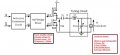
I have attached my system block diagram for elaborating my question. Short summery of Project:
I am desired to auto-tune tank circuit between amplifier and ultrasonic transducer to power it effeciently and reduce losses. I have freedom to varing capacitor only and to keep the inductor value minimum (constant) in order to reduce EMI of inductor (which can influence MRI (performance), used along with ultrasonic transducer). A PWM control signal is used to control Variable capacitor such that amplifier power is exacely matched with transducer. A robust isolation technique is resquested which can isolation AC switch driver(5V) from Control switches (260Vp-p).
Thanks @Janis59@Irving@AnalogKid for your responses.
I have attached my system block diagram for elaborating my question. Short summery of Project:
I am desired to auto-tune tank circuit between amplifier and ultrasonic transducer to power it effeciently and reduce losses. I have freedom to varing capacitor only and to keep the inductor value minimum (constant) in order to reduce EMI of inductor (which can influence MRI (performance), used along with ultrasonic transducer). A PWM control signal is used to control Variable capacitor such that amplifier power is exacely matched with transducer. A robust isolation technique is resquested which can isolation AC switch driver(5V) from Control switches (260Vp-p).
If the input to your 1/2 bridge driver is logic level, either 3.3 or 5v then the Maxim devices I linked to would suffice. The half-bridge driver would need its own power supply on the HV side. There are many half-bridge drivers, e.g. ST L6393, TI UCC27714, Infineon 2ED21824S06J, etc. etc.
Alternately, why not look at 1/2-bridge drivers with built-in isolation, e.g. Analog's ADuM3223/5223/7223 series, ST's STGAP2D, etc., etc.
 Facebook
 Google
 GitHub
 Linkedin