Faulty Flowmeter, Floating DC circuit and Galvanic Isolation design

Thread Starter

curiousMal

Joined Aug 9, 2018
3
Hi,

I am new to the forum, and have a beginners level knowledge of circuit design.

System Information
I have a system with a mains powered 240VAC control unit.
The control unit has a 240VAC and 5VDC side, with galvanic isolation beween the two, possibly achieved by a transformer, followed by some form of rectifier for the AC - DC conversion, I don't know the internal design.
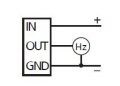
I have a flow meter wired to the controller's 'Low voltage' (LV) side, with 3 wires as per the attached image, labelled as follows.
1. A +5DC supply
2. A GND return
3. A pulse frequency return signal
[?]I don't exactly understand this, is it constant current, variable frequency?

One can measure the frequency rate of no.3 in Hz, and convert that to a flow rate using a table.

The Problem
In a 0L/min no flow case, the flowmeter outputs (in error) 50Hz, and the controller thinks there is a ~4L/min flow and takes action.

What I've tried

(I) Bonding pipework: Makes no difference

(II) Bring the unit to another country, with a 'cleaner' power supply: Makes no difference

(III) Hard wiring the controller GND connection to an external Earth terminal also: Issue fixed.
I have been told by the controller manufacturer that this is very 'dangerous' and should not be done.
[?] How dangerous is it? If a user touches a live +5VDC wire on the LV side with a earth in place current will flow.

The - or 0VDC connection on the controller is actually at a measurable 45mV relative to Earth. Does that mean the LV side is floating?
[?] Would a component that needs a 5VDC supply react give errors due to this potential above Earth.
[?] Does LV GND as specified by the flowmeter manufacturer mean it should be at 0V relative to Earth, or would 5VDC supply in a floating system be ok.

Thank you in advance for your help. If you need more info please comment.


Attachments

ebp

Joined Feb 8, 2018
2,332
Do you have a datasheet for the flow meter?

Outputs of such devices are very often (Burtus's post popped up mid-sentence) designed to only "sink" current - when the output should be logic LOW ("zero") an active device such as a transistor connects the output pin to the circuit common. When the output should be logic HIGH ("one") the output is open-circuit. When it is open circuit it is very susceptible to pickup of noise, and very often the noise is a AC mains frequency.

To use an open-collector output, a "pullup" resistor is required. This connects between the signal output and the positive power supply of whatever is receiving the signal. The resistor assures a good logic HIGH and reduces the impedance so that noise coupling is dramatically reduced. The value of pullup resistor used can vary greatly. Often a value that would result in a current of a few milliamps if connected directly across the power supply of the receiving circuit is appropriate. With the receiving circuit powered with 5 volts, that would mean a resistor in the range of perhaps 500 ohms to 5000 ohms. I would probably use something in the range of 1k to 2k ohms unless the spec's for the flow meter had a recommendation. Sometimes receiving circuitry, particularly something like a microprocessor input, will have a pullup resistor, but often one of very high resistance, just to be sure the input doesn't float.

"Open collector" is a term that comes from using an NPN transistor as a "common emitter" switch - the emitter goes to circuit common and the collector, with nothing connected to it, is the output.

Often the low voltage common is floating relative to earth ground. Whether this is good, bad or indifferent is not always easy to assess. It is also extremely common for it to be connected to earth ground.
 
50 Hz is suspicious. i.e. mains frequency

The output is likely open collector. See https://en.wikipedia.org/wiki/Open_collector There should be a sink current spec that you should not exceed. You can think of this as a contact closure to ground or "almost ground".

The open collector output allows you to interface with nearly any logic level e.g. 5V, 24 V

An open collector output needs a pull-up resistor (to the logic supply) to function unless the uP has one built in.
 

MaxHeadRoom

Joined Jul 18, 2013
28,619
(III) Hard wiring the controller GND connection to an external Earth terminal also: Issue fixed.
I have been told by the controller manufacturer that this is very 'dangerous' and should not be done.
[?] How dangerous is it? If a user touches a live +5VDC wire on the LV side with a earth in place current will flow.
I cannot see how this is dangerous if you have galvanic isolation from the service mains and earth ground a 5v supply, the 5v should present no danger to anyone coming in contact with it.
Max.
 

Thread Starter

curiousMal

Joined Aug 9, 2018
3
Hi,

Thank you for the replies. It will take me a while to understand them and form an intelligent response, I'll need to do the background readings in the links.

See the attached flow meter spec.

I tried changing the flowmeter to another unit with NPN Open Collector (see attached image). It did not work. Can you comment on different types of open collector : eg NPN, PNP?
Is the design flaw that causes the error in the controller hardware, or in the flowmeter?

Thanks again
 

Attachments

ebp

Joined Feb 8, 2018
2,332
I would interpret the datasheet to mean that the output is not open collector. It does specify a rather high load resistance (10k ohms), which is a bit surprising.

If I'm right, that unfortunately puts us back to the beginning to try to sort out what is wrong.

I agree with Max - I just don't see how connecting the low voltage common to earth ground could be dangerous. I'd be willing to bet that 99% or more of industrial equipment has such a connection.

Many/most switch mode power supplies have a capacitor connected between the low voltage common and some point on the high voltage side, often the negative of the rectified input. The purpose of this is to provide a local "return" path for high frequency energy to reduce radio frequency interference. This means there is a path for a small amount of current from the AC mains to the secondary side, but the amount of capacitance is small to limit this current and the type of capacitor used is specified for safety for exactly this application (more or less "double insulated" so two internal faults are necessary to make it a safety hazard). Making a hard connection from secondary common to mains ground won't "undo" the benefit or safety.
 

ebeowulf17

Joined Aug 12, 2014
3,307
What is the connection from sensor to controller like? How long are the wires? Are they shielded and/or twisted? Do they run through conduit? How close do they run to high voltage wires? When they're near high voltage wires, do they run parallel, or do they only cross at perpendicular intersections?

That data sheet leaves a lot to be desired in my opinion. There's no mention of what kind of load the output can drive (what sort of input impedance the controller should have.)

If this were my sensor, I'd do some experiments to test the limits of acceptable controller input impedance. First disconnect the sensor and measure voltage from the controller's sensor input to ground, and then input to 5V supply. Presumably there is either a pull up or pull down resistor so that the input is never left floating. You don't want to fight against it, but you could make it stronger.

For example, if you measure 0V between input and supply and 5V between input and ground, you know you've got a pull up resistor keeping the input at supply voltage when it would otherwise be floating. Now you can try adding another resistor in parallel from input to supply, effectively lowering the input impedance and making it more resistant to external noise. You might try a series of values, like 10k, 3.3k, 1k, 330. I suspect that at some point the resistance gets too low and stops the signal entirely. Maybe if you're lucky there's some value in between that reduces noise without harming your signal. I could also be off my rocker on this one... I've never actually done what l described above, I'm just brainstorming and thinking out loud.
 
Agree with edp:

Ground loops are possible though. Shield connected to ground at two places. GND connected to ground at two places.

Common wire is twisted pair shielded. When you use this wire, the shield gets connected at ONE END only. If the source has a decent connection to earth, then it's usually the source end.

Now, we need to now a little about the input it's connected to.

A statement in the specs doesn't make sense. "Load against GND or IN"
 

MaxHeadRoom

Joined Jul 18, 2013
28,619
Siemens have a good paper on grounding of equipment including equip-potential bonding where this is done correctly the shielded conductor can be connected to GND at both ends and star earth connection method is used.
Max..
 
That makes sense.

Ground loops are easy to avoid except when they're not.

I did get burnt when modifying a home built device to be computer controller. It worked great stand-alone. It considted of 6 10 T potentiometers, a +-15 V power supply and a 5V power supply.

6 Mass flow controller boards located about 15' away from the controller.

The setpoint was relative to the card, not the neg of the 5V supply. I missed that. Current output usually saves the day, but I didn't have it.
Work bought a 4-channel device with one readout and not the 6 readout device I had. I wasn't given the opportunity to fix it.
 

ebp

Joined Feb 8, 2018
2,332
It occurs to me that perhaps the controller to which the flow sensor is connected is excessively (for the requirement at hand) sensitive, possibly even employing some sort of automatic gain control, though I think that is unlikely. For a simple flow sensor with something like a magnet moving past a pickup coil each revolution, the output signal amplitude would be inversely proportional to flow rate and quite high sensitivity would be necessary at low flow. For the sensor being used, the amplitude is independent of speed (I think - back to that dubious datasheet).

Is documentation available for the controller, at least sufficient to determine what it expects for input?

If it is too sensitive, it is likely possible to reduce the sensitivity sufficiently to reject line-frequency noise without rejecting the signal from the flow meter. For example, you might use something like a 1k resistor from the controller's input to it's common (signal ground) and a 10k resistor between the input and the cable connecting the flow meter sensor to the controller. That might not be the optimal ratio - I've just tossed it out to illustrate the general idea.
 

Thread Starter

curiousMal

Joined Aug 9, 2018
3
Hi

The wires are only short between the flow sensor and the controller, <1meter, and do not run through trunking or near any high voltage wires.
Unfortunately the controller manual is very high level, and gives even less details that the flow meter manual.
 
Top