Facebook
 Google
 GitHub
 Linkedin
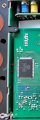
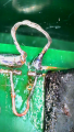
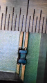
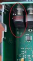
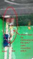
I am hoping you kind people on this forum can help me figure out what i need to repair a very expensive and out of warranty piece of equipment. It is an EEG amplifier which connects to the computer via a USB cable. When plugged in, it is not being recognized by the computer. Ive narrowed it down to a fault in the USB data circuit (see troubleshooting1.jpg and a blown up version in troubleshooting4.png). This is my first time opening this up, but it seems at some point someone really did a number on the trace (D- or D+) exiting the USB terminal.
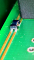
I wanted to bypass this broken circuit with a jumper cable attached to the other side of the board. I dont trust my ability to fix the broken trace. I want to know what the black component is on the bottom half of troubleshooting4. A naive search led me to "transient voltage suppression diode", but i have no idea what kind. Seems important.
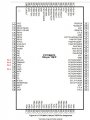
In case it is relevant, after the data lines pass through this component, they go to the D-/D+ terminals of this chip CY7C68013A-100AXC | USB 2.0 Peripheral controller with 16K RAM, 40 GPIOs, serial debug, 100-pin TQFP for non-battery powered applications - Infineon Technologies
I really appreciate any help you can give!
-Andrew
I wanted to bypass this broken circuit with a jumper cable attached to the other side of the board. I dont trust my ability to fix the broken trace. I want to know what the black component is on the bottom half of troubleshooting4. A naive search led me to "transient voltage suppression diode", but i have no idea what kind. Seems important.
In case it is relevant, after the data lines pass through this component, they go to the D-/D+ terminals of this chip CY7C68013A-100AXC | USB 2.0 Peripheral controller with 16K RAM, 40 GPIOs, serial debug, 100-pin TQFP for non-battery powered applications - Infineon Technologies
I really appreciate any help you can give!
-Andrew
Attachments
-
 122.7 KB Views: 22
 -
 445 KB Views: 22