Gain transistor

Thread Starter

SneakSZ

Joined Sep 19, 2012
10
Hello guys,

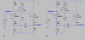
I'm trying to found out Av1(gain from Q4) of the schematic below.


I thought this would be -(RinQ3//R4)/(reQ4+R7).
with RinQ3 = (BetaQ3+1).reQ2 = BetaQ3*26mV/IcQ3.
Took BetaQ3 as 300 and IcQ3 was 6.65 mA
RinQ3 = 300*26V/6.65A~ 1K2
RinQ3//R4 ~ RinQ3
ReQ4 = 26mV/IcQ4 with IcQ4 = 0.7V/15K = 46.6µA
= 560 Ω
Av1 = -1K2/(1560Ω)=- 0.77

The LTSpice result gave me a gain which was arround 0.16..
The voltage at node4 is VcQ4


I'm unable to found out what I'm doing wrong.

Someone could help me out on this one?

Thanks in advance!!

The LTSpice file is in the att.

Original link : http://www.zen22142.zen.co.uk/Circuits/Audio/2wamp.html
 

Attachments

Thread Starter

SneakSZ

Joined Sep 19, 2012
10
Hello t_n_k, well thats just some filtering of the power supply.
At AC, it's shorted due to the source/C5 (on my schematic, R6 on zen's).
 

ericgibbs

Joined Jan 29, 2010
18,848
hi SZ,
LTSpice confirms that it is attenuated by ~-16dB at Q4 collector.

The low Base Emitter resistance of Q3 is in parallel with R3, so the total load resistance is ~150R.

If you add a 3K3 resistor between Q4 collector and Q3 Base you will get ~ -2dB ie: 0.77

E
 
Last edited:

Thread Starter

SneakSZ

Joined Sep 19, 2012
10
hi SZ,
LTSpice confirms that it is attenuated by ~-16dB at Q4 collector.

The low Base Emitter resistance of Q3 is in parallel with R3, so the total load resistance is ~150R.

If you add a 3K3 resistor between Q4 collector and Q3 Base you will get ~ -2dB ie: 0.77

E
Hello EG,

could you tell me how you got a total load resistance of 150R?

Kind regards!
 

Thread Starter

SneakSZ

Joined Sep 19, 2012
10
There is no easy way to find the Q4 voltage gain. Because we need to include R5 effect on the voltage gain. To do so you need to do the full circuit small-signal analysis.
Try read this thread
http://forum.allaboutcircuits.com/showthread.php?p=711574#post711574
Hello Jony,

yes, I saw that analyse methode before but I thought I could exclude the influence because the feedback resistor, R5, is << R4 so it sees a large impedance and therefore I excluded it.

I thought I could calculate the Aol (exclude R5) and then R4 and R5 form the feedback so I get the closed loop gain.
 

Jony130

Joined Feb 17, 2009
5,488
Ok so you what open loop gain ?

AvQ4 = (R5||((β +1 )*reQ3))/(R4 + reQ4)

reQ3 = 26mV/Ic = 3.9Ω

reQ4 = 26mV/Ic = 330Ω

AvQ4 = (R5||((β +1 )*reQ3))/R4 = 1.1K/ 1.33k = 0.75V/V

But you in post one show as that LTSpice result gave me a gain which was around 0.16V/V
But this gain shown by LTspice is a Q4 gain but with closed loop gain.

And this gain will vary with the load. Without the load resistance the Q4 gain drop to 83mV/V.
 

Attachments

Thread Starter

SneakSZ

Joined Sep 19, 2012
10
Siema Jony,

thanks a lot for the insight and the analysis. I understand your post (Post 8).
Well the gain of 0.16 for Q4 with the closed loop gain is the thing I don't understand.

Could you explain to me how that value (0.16) is achieved?
It's the more or less the same question I asked Eric (load impedance of the collector of Q4).

Kind regards.
 

Jony130

Joined Feb 17, 2009
5,488
I use Jacob Shekel method and math software and I find a symbolic expression for Q4 voltage gain (I simplify circuit a bit). And as you can see in this form we have no use for this expression. And this is why for such a circuit we only use numerical solution.
 

Attachments

Last edited:

Thread Starter

SneakSZ

Joined Sep 19, 2012
10
Hello Jony,

thanks for the reply and all the effort. I understand the analysis (used it before) and it gives indeed Voltage gain V3 = -0.158582.

I'm trying to figure out why Eric had a total load resistance (for Q4) of 150Ω.
This is not the same as the one 1 calculated in my first post.

You have an idea?

Kind regards!

hi SZ,
LTSpice confirms that it is attenuated by ~-16dB at Q4 collector.

The low Base Emitter resistance of Q3 is in parallel with R3, so the total load resistance is ~150R.

If you add a 3K3 resistor between Q4 collector and Q3 Base you will get ~ -2dB ie: 0.77

E
 

Thread Starter

SneakSZ

Joined Sep 19, 2012
10
Ok so you what open loop gain ?

AvQ4 = (R5||((β +1 )*reQ3))/(R4 + reQ4)

reQ3 = 26mV/Ic = 3.9Ω

reQ4 = 26mV/Ic = 330Ω

AvQ4 = (R5||((β +1 )*reQ3))/R4 = 1.1K/ 1.33k = 0.75V/V

But you in post one show as that LTSpice result gave me a gain which was around 0.16V/V
But this gain shown by LTspice is a Q4 gain but with closed loop gain.

And this gain will vary with the load. Without the load resistance the Q4 gain drop to 83mV/V.
I'm unable to open the .asc, LTspice couldn't find the i_of_i_1ue voltage3.
It's the current amplifier, any idea how to open this file or select this current amplifier from the libs (can't find it)?

I use the latest LTspice version.
 

Jony130

Joined Feb 17, 2009
5,488

ericgibbs

Joined Jan 29, 2010
18,848
hi SZ,
Ref your PM.
To show the open loop gain of your Amp I have removed the negative feed back resistor from the output and connected it to a 7.5V source.
Ran an AC analysis, the gain at Q4 collector is close to your calculated value of ~ -3dB, the BF=200 for a 2N3904.

E
 

Attachments

Top