Facebook
 Google
 GitHub
 Linkedin
hello all
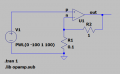
I have been trying to get my head around what the gain means in a transistor and op amps, I thought I had it and realised I don't, I have read numerous articles on here and numerous responses regarding what it is, and it still just isn't enough for me to get my head around, so this is my thoughts on it please correct me and ill hopefully I can get my head around it.
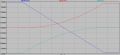
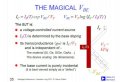
from what i can read it almost defies logic on how gain works, how can say an op amp gain more then the input voltage? how can it gain from thin air, and regarding a transistor say a MJ3001 where gain is explained in a datasheets, it suggests gain is how much it will take before it breaks down as the amount it takes matches the ampage rating.
what am i missing thanks in advance, might be a stupid question to some of you.
I have been trying to get my head around what the gain means in a transistor and op amps, I thought I had it and realised I don't,
I have read numerous articles on here and numerous responses regarding what it is, and it still just isn't enough for me to get my head around, so this is my thoughts on it please correct me and ill hopefully I can get my head around it.from what i can read it almost defies logic on how gain works, how can say an op amp gain more then the input voltage? how can it gain from thin air, and regarding a transistor say a MJ3001 where gain is explained in a datasheets, it suggests gain is how much it will take before it breaks down as the amount it takes matches the ampage rating.
what am i missing thanks in advance, might be a stupid question to some of you.