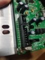
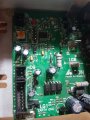
g Treadmill (Proform/Domyos) controller board Fault

MaxHeadRoom

Joined Jul 18, 2013
28,617
I'm not actually familiar with the unit in person, I am not sure what the -ve terminal refers to? Do you need it?
If you did not add the resistor you could have blow tne opto, there is only a 22ohm resistor in series , you need to add a resistor to ensure a max current of 50ma or LESS.
 

Thread Starter

MihaiBrB

Joined Mar 19, 2022
48
I'm not actually familiar with the unit in person, I am not sure what the -ve terminal refers to? Do you need it?
If you did not add the resistor you could have blow tne opto, there is only a 22ohm resistor in series , you need to add a resistor to ensure a max current of 50ma or LESS.
yeah.no resistor added
 

Thread Starter

MihaiBrB

Joined Mar 19, 2022
48
I'm not actually familiar with the unit in person, I am not sure what the -ve terminal refers to? Do you need it?
If you did not add the resistor you could have blow tne opto, there is only a 22ohm resistor in series , you need to add a resistor to ensure a max current of 50ma or LESS.
yeah.now the led of blinking even without pwm.maibe the opto ia dead..anyway i will replay it but i dont know what resistance to add to limit the curent to 50ma.and where to add it
 

MaxHeadRoom

Joined Jul 18, 2013
28,617
I don't think you will need the -ve out term.
If you measure the right voltage value from + to gnd then probably not.
A suitable resistor goes in series with the PWM lead.
 

Thread Starter

MihaiBrB

Joined Mar 19, 2022
48
I don't think you will need the -ve out term.
If you measure the right voltage value from + to gnd then probably not.
A suitable resistor goes in series with the PWM lead.
yes.ve- was not needed.got a discharge in the light bulb ...hmm.i just conected the pwm pin the 9v pin and GND from module to GND from board.20 hz and 16% duty.the light bulb stayed on for 6 sec them off :)) i am getting closer
 

Thread Starter

MihaiBrB

Joined Mar 19, 2022
48
So it appears you need a 470Ω series resistor in the PWM lead , when it work, (PWM in) the LED starts to flash steady.
yeah added the resistance..just sometimes it lights up (the light bulb connect to the motor side) for a few seconds..them goes off.

I just wanted to add tha fact that i use a dim light bulb before feed 230 Ac.
Anyway i think its impossible to emulte the pwm to replace the upper console :(
 

MaxHeadRoom

Joined Jul 18, 2013
28,617
Anyway i think its impossible to emulate the pwm to replace the upper console :(
Not quite true, ?
Not only have I provided the board I made up to a few, there are many that have made up one of the circuits, 555 etc, that are out there on the WEB.
I have 3 different versions of the MC2100 here at present running that way.
 

Thread Starter

MihaiBrB

Joined Mar 19, 2022
48
Not quite true, ?
Not only have I provided the board I made up to a few, there are many that have made up one of the circuits, 555 etc, that are out there on the WEB.
I have 3 different versions of the MC2100 here at present running that way.
this is the version.
when powered up the red led blinks like 1/sec ..when sometimes gets pwm for a few sec it lights very fast them when pwm stops, the led stays on(never blinks)
 

Attachments

Last edited:

MaxHeadRoom

Joined Jul 18, 2013
28,617
I have found all the variations of the MC2100, they are basically identical in general design, just some component and circuits are different, but they all obtain the same result.
Are you sure the 20Hz is set, you can even vary this to see if there are any changes, It would seem obvious the boards you show seem to use exactly the same method of control, i.e. 20Hz PWM.
 
Top