Function of paired inverters?

Thread Starter

metermannd

Joined Oct 25, 2020
472
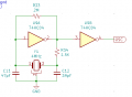
I'm curious about the paired inverters and resistor / cap combination and their function. What does it accomplish?

Is it necessary to use a 74x04 or can the same thing be accomplished with a bipolar transistor equivalent?

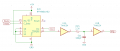
The ASIC is a multi-section IC; this is the main portion while the remainder is a trio of analog switches. CLK is a 1 MHz reference input, Mode sets the state of the analog switches, Data is the bit stream from the MPU, and IRQ is a ~2.5 kHz square wave that drives the MPU's interrupt line. S0-S2 selects the operating frequency (in this case, 12.5 kHz).
 

Attachments

Rf300

Joined Apr 18, 2025
72
It would be better to use 74HC14 instead of 74HC04 because of the schmitt-trigger input. Digital ICs have a maximum input rise time specified in the datasheet. If this exceeded, the output may show strange behaviour like bouncing. With a time constant of 220 ns, like in this case, it may work, but it is always better to be on the safe side.
 

Thread Starter

metermannd

Joined Oct 25, 2020
472
That would make sense re: blocking false IRQs. As for the original circuit, the six inverters on the 74HC04 are broken out into pairs - one delay for the IRQ line, one delay for the SCK line on some memory driven by the MPU's SPI bus, and the other pair is the master oscillator.

On a related tangent - is there much difference between using a dedicated oscillator (the type in a metal can) or an oscillator circuit using the aforementioned pair of 7404s? (i'll clip the bit from the schematic, but it's pretty late at the moment)
 

Irving

Joined Jan 30, 2016
4,996
On a related tangent - is there much difference between using a dedicated oscillator (the type in a metal can) or an oscillator circuit using the aforementioned pair of 7404s? (i'll clip the bit from the schematic, but it's pretty late at the moment)
Depends on how accurate/stable you want the frequency to be, assuming the 74HC04 are not associated with a crystal or ceramic resonator.
 

Rf300

Joined Apr 18, 2025
72
If you need a precise frequency, i would recommend the dedicated oscillator. It is a simple plug and play solution that will always work, you simply have to select the desired frequency and the correct output oltage (TTL or CMOS 3.3V, 2.5 V, 1.8V). You should use a crystal only in connection with a dedicated crystal oscillator circuit which is integrated in most microcontrollers or some peripherals which need a precise frequency (e. g. Ethernet PHYs). They all have dedicated XTALIN and XTALOUT pins. Between them there is an integrated ANALOG amplifier which is specially designed for a crystal oscillator.

All oscillators with 74xx04 may work. But in this forum there are a lot of threads from guys who didn't get them running. Those 74xx04 solutions are only for tinkerers, because the function of this circuit is not reliable. In my company those circuits are not allowed in a HW-design. Always remember: these circuits are violating a DIGITAL gate as an ANALOG amplifier. For a tinkerer's one piece solution it may work because he can tune the circuit to be working under the special conditions of this individual circuit. But: is it worth tinkering hours to get such a circuit running versus about 1 $ which might be the additional costs of an integrated crystal oscillator?
 

Thread Starter

metermannd

Joined Oct 25, 2020
472
I looked at the various boards I've reverse engineered, and it is just this one generation that used this "oscillator". It now seems to me it's because the MPU in this case is the stripped-down 68HC05C9A MPU... seems it doesn't have a divider with external output (this "oscillator" is also accompanied by a 7474 that is wired for divide by 4).

Everything else in my files used canned oscillators (whether the odd EG&G Cinox TCXOs or modern DIP-14 units) or used a standard crystal that fed into the 68xx MPU to generate the system clock.
 

Attachments

Thread Starter

metermannd

Joined Oct 25, 2020
472
Coming back to the original question, I swapped the 74x04 for a 74x14, then swapped the SOIC-14 for a pair of SOT-23-5 units as this adaptation only needs two of the six sections. No sense in taking up real estate with the full package.
 

Irving

Joined Jan 30, 2016
4,996
I looked at the various boards I've reverse engineered, and it is just this one generation that used this "oscillator". It now seems to me it's because the MPU in this case is the stripped-down 68HC05C9A MPU... seems it doesn't have a divider with external output (this "oscillator" is also accompanied by a 7474 that is wired for divide by 4).

Everything else in my files used canned oscillators (whether the odd EG&G Cinox TCXOs or modern DIP-14 units) or used a standard crystal that fed into the 68xx MPU to generate the system clock.
This use of an inverter with an xtal or ceramic resonator was quite common in the early days of embedded 8-bit MCUs running at speeds <=4MHz where external clocks were needed; I recall several projects using the technique in the 1980's, especially where the MCU was accompanied by a horde of TTL logic. Now its rare to see even a canned TCXO as many MCU have embedded oscillators with laser-trimmed & temperature compensated precision. Even a lowly ESP32 SoC module has a tiny 40MHz xtal and a 6x PLL to generate an internal 240MHz CPU clock.
 
Top