 Facebook
 Google
 GitHub
 Linkedin
Howdy,
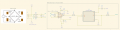
I'm designing some circuity that will provide a clean, amplified output signal from a strain gauge and would love to hear some feedback!
I'm designing some circuity that will provide a clean, amplified output signal from a strain gauge and would love to hear some feedback!
- Should I have the R1 & R2 resistors between the gauge & diff amplifier? I saw another design use these but in my head I'm thinking that they would cause a voltage drop of 1% error before reaching the amp, so perhaps it would be best to omit them.
- I am trying to write a transfer function to relate the voltage at AnaOut to Force in newtons. Has anyone here used a 350oHm full bridge gauge that knows how much force is required for a full scale voltage reading? I will then use a relationship to relate percentages of full scale.
Attachments
-
 90.8 KB Views: 26


