Fried my transformer, need help

Thread Starter

DesertCrawler

Joined Feb 5, 2020
32
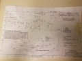
Hey everyone! I am relatively new to electronics and need some help. I am building a plasma arc modulator and everything has gone smooth until I tried adding the transformer. I plugged it in and it begun to spew smoke. I just got a replacement and I do not want to ruin this one considering it was $60
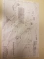
There are 2 black leads and 3 green leads, one with yellow as the ground. diagram.JPG

How do I identify where to properly put these leads?
 

Reloadron

Joined Jan 15, 2015
7,501
You have a transformer which has an AC out delivering to a board clearly labeled In + and In - which tells me the board expects a DC input. That is likely a big problem. How much DC power does the board require and at what voltage?

Ron
 

Dodgydave

Joined Jun 22, 2012
11,284
The Black leads are the Primary windings Mains input.

The Greens are the Secondary windings with the Yellow as the centre tap,.
Your pcb expects a DC input,!!!

How did you blow up the transformer?
 

Reloadron

Joined Jan 15, 2015
7,501
Why they would label a board with IN + and In - when they expect an AC input is totally beyond me. You only use the two green wires, the green/yellow is a transformer CT (Center Tap) so just tape it off, it is not used. You want a transformer secondary of between 48 and 70 VAC @ 2.0 Amps. It looks like the In + and In - run through a fuse and then a bridge rectifier. Normally a transformer will hack even a short for a short period (minutes) before it cooks and since there is even a fuse in there I have no idea how you cooked one?

Ron
 

AlbertHall

Joined Jun 4, 2014
12,343
That should be fine if your supply voltage is 115V.
If it fried then there must be a problem with the board: Splash of solder shorting something, component the wrong way round, or something similar.
 

Thread Starter

DesertCrawler

Joined Feb 5, 2020
32
Another thing I am confused about is, the fuse it runs through blew but the transformer still fried so is it really the board? i really appreciate yall helping. I bit off a little more then i can chew and this project was over $300
 

AlbertHall

Joined Jun 4, 2014
12,343
Another thing I am confused about is, the fuse it runs through blew but the transformer still fried so is it really the board? i really appreciate yall helping. I bit off a little more then i can chew and this project was over $300
Is the fuse connected before or after the rectifier?
What rating was the fuse?
 

AlbertHall

Joined Jun 4, 2014
12,343
5A is a very big fuse for a 2A transformer.
Are you sure that the rectifier is the right way round? (Notched end should connect to the square pad)
What is your supply voltage? Are the jumpers correctly installed?
Can you post the schematic here please.
 

Reloadron

Joined Jan 15, 2015
7,501
I can't understand why a transformer rated for two amps would be fused at five, I can't see where a circuit like this would have any surge to speak of at turn on. When the last transformer cooked what happened? You applied power and... ? Those transformers are really pretty hard to kill. The rectifier is a 4 Amp bridge. The jumpers are mentioned on page 20. I wish there were an actual schematic. That would make things easier.

Ron
 

Thread Starter

DesertCrawler

Joined Feb 5, 2020
32
I can't understand why a transformer rated for two amps would be fused at five, I can't see where a circuit like this would have any surge to speak of at turn on. When the last transformer cooked what happened? You applied power and... ? Those transformers are really pretty hard to kill. The rectifier is a 4 Amp bridge. The jumpers are mentioned on page 20. I wish there were an actual schematic. That would make things easier.

Ron
I was at page 34. I plugged it in and was about about to start step 8. The fuse had already blown but I did not realize it. About a minute after plugging it in the transformer begun the spew smoke i am starting to feel the engineer of this kit did a poor job.
 

Reloadron

Joined Jan 15, 2015
7,501
The F42 fuse reflects being 3.0 Amp then the bridge which you said is keyed correctly followed by a 2 watt bleeder resistor and the choice of filter caps. Something in here is loading that supply and it's a pretty basic crude supply. If you have a meter you could start bu working through the bridge rectifier and measuring across the DC supply. Would you be familiar with how to check components like this?

Ron
 
Top