Frequency Detection Circuit from Summed Signal Input.

Thread Starter

Elbobboo

Joined Mar 24, 2023
12
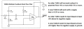
I am required to design a circuit that detects within a signal if a certain frequency wave is present (V1,V2,V3).
The input (Vt) signal is a combination of three separate signals added together.
V1 = 0.5 * sin(2 * pi * 100 * t)
V2 = 0.5 * sin(2 * pi * 1000 * t)
V3 = 0.5 * sin(2 * pi * 10000 * t)
Meaning Vt could be
Vt = 0.5 * sin(2 * pi * 100 * t) or 0.5 * sin(2 * pi * 100 * t); + 0.5 * sin(2 * pi * 1000 * t).
A quick matlab plot of the wave forms.
Capture.PNG

I have gone down the path of having three parallel band pass filters design for 100Hz, 1000Hz and 10000Hz.

Circuit1.png

However this only works if the individual wave forms are present (V1 or V2 or V2) not in combination.
Is there a better method?Or other way?
The idea is to trigger a separate circuit, if that frequency is present. Such as a light for 100Hz or a motor for 1000Hz.
 

WBahn

Joined Mar 31, 2012
32,703
When you say that it doesn't work if the waveforms are in combination, what do you mean? In what way doesn't it work?
 

Thread Starter

Elbobboo

Joined Mar 24, 2023
12
When you say that it doesn't work if the waveforms are in combination, what do you mean? In what way doesn't it work?
I originally was using Circuit-Lab however couldn't get the three waveform in combination. I transferred it to Lt Spice (Which i only downloaded/learnt how to use for this exercise) and got these.
Due to the combination the circuit wouldnt see 100Hz and 1000Hz it would see the modulated signal. circuit.PNGCapture.PNG

The intention it go have,
 

Attachments

Ian0

Joined Aug 7, 2020
13,097
Your op-amps need a negative supply.
How are you expecting to produce and output signal that goes both positive and negative without it?
 

Papabravo

Joined Feb 24, 2006
22,058
If you are going to configure the signal sources with bipolar sinewaves, shouldn't the opamps in the filter sections be configured with bipolar supplies? Alternatively, you could bias the opamp inputs at 2.5 VDC (aka one-half of the opamp supply voltage) and AC couple the signal sources. You could also add a DC component to the signal sources and remove it by AC coupling the sources to the filter inputs. What you have will give you problems.
 

crutschow

Joined Mar 14, 2008
38,317
Your filters have poor band-pass response, especially the 100Hz one.
Where did you get those RC component values, as they are not correct?

Here's one design tool that can help you with the values.
 

Papabravo

Joined Feb 24, 2006
22,058
Yes, that was the link I intended to post.
Don't know how it came up as the lowpass filter one.
Happy to hear it was just a minor oversight. They all have such a similar "look and feel", suggesting mistakes might be an occasional occurrence.

ETA: I'm curious to know if the TS has any experience in selecting the corner frequencies for a bandpass filter. In this case we suspect that the frequencies of interest will be in the "middle" of the passband. What does that mean exactly in the case of frequencies? Some might be quick to posit that the frequency in the middle or center of the passband should be the arithmetic mean of the two frequencies. Turns out this will not work. You should select the corner frequencies of the passband by setting them to the geometric mean.

For example, for the 100 Hz filter the geometric mean of 85 Hz. and 120 Hz is computed as:

\( \sqrt{{85\text{ Hz.}}\times{102\text{ Hz.}}}\;=\;101\text{ Hz.} \)

Which is close enough for government work.

If you want a higher Q filter with steeper skirts, then another topology besides the MFB Bandpass filter is required.
 
Last edited:

Ian0

Joined Aug 7, 2020
13,097
They all have such a similar "look and feel",
There are five components, each of which can be either a resistor or a capacitor, and three designs that I know of: low-pass, high-pass and bandpass. I assume that there might be an allpass and a notch. That takes care of 5 combinations of a possible 32. One will be all resistors, which will make an inverting amplifier, and one will be all capacitors. I wonder what the other 27 possibilities do.
 

Papabravo

Joined Feb 24, 2006
22,058
I apologize. I thought the design program would let you specify the 3 dB points. Turns out you specify a "center frequency" and you get a second order rolloff.

1721584139350.png

Turns out the bandwidth of the second order MFB bandpass is ≈ 139 Hz. It is still true that the center frequency is:

\( \sqrt{{191.896}\times{53.232847}}\;\approx\;101.07\text{ Hz.} \)

To get a steeper rolloff you would need to cascade multiple 2nd order sections and possibly a single first order section to make a higher order filter.
 

Thread Starter

Elbobboo

Joined Mar 24, 2023
12

Papabravo

Joined Feb 24, 2006
22,058
Hey yes I did. Originally using Circuit Lab as that is the "preferred" simulator for my course I ended up with this.
View attachment 327536I used the OKAWA Electric Design MFB Band Pass Filter calculator, to obtain the resistor values as I am stuck with using, only 6 possible caps (3x 4.7nF, 2x 22nF and 1x 47nF).
The requirement for using specific capacitor values was never explicitly stated. It was however implied by your original schematic.
When I try to use the Okawa-Denshi tool for a bandpass filter of 101 Hz. with equal 4.7nF capacitors it throws an error message saying such a thing is not possible. Either I'm doing something wrong, or you are. When you specify the equal capacitor values there are additional requirements that must be satisfied:

\( \cfrac{C_2}{C_1}\;\ge\;4\zeta^2|K|-1 \)
\( \cfrac{C_2}{C_1}\;\ge\;\cfrac{|K|}{Q^2}-1 \)

Turns out a Q factor of 1 and a damping ratio ≈ 0.5 gives very high resistor values and a somewhat ugly transient response, with considerable overshoot. I notice that my transition bands, away from the peak, are straight and linear whilst yours have a breakpoint and are piecewise linear. Can you explain that? It seems like a suspicious artifact of your simulator.

1721660017987.png
 
Top