FM Transmitter - Breakdown & Analysis

Audioguru

Joined Dec 20, 2007
11,248
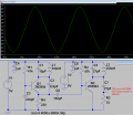
C3 shorts the +9V to ground at the RF frequency so that the +9V does not swing up and down with the RF which would cancel the RF. The battery cannot short the RF to ground because it has its own resistance plus the inductance of the wires from the battery to the circuit. What is an inductance? It is a high resistance at the RF frequency. All active electronic circuits need a supply bypass capacitor like C3 is.
 

Thread Starter

Max Kreeger

Joined Oct 1, 2013
95
Thanks NsaSpook, I'll definitely have to revisit the basics..


I made a simulation of the FM circuit in question, but removed the audio input to see what would happen.

Note:
The output wave is from the antenna.
Also disregard the extra resistors in line with the capacitors (simulation wouldn't run without them).

My question is this...the battery voltage goes down the 4.7K resistor and powers the base past 0.7...turning the transistors on...this allows voltage to take the inductor path to ground...at the same time not giving any voltage to the base...this creates a switching action.

So if there was an audio input..does that mean only segments of the audio input are actually used to modulate since the switching is dictated elsewhere? When the BJT is off...the signal is wasted and does nothing until the BJT is back on? Hopefully that made sense.


Side note: How were the feedback capacitor and battery bypass capacitor calculated? Whats that based on?
Sim1.png
 

DickCappels

Joined Aug 21, 2008
10,661
Your simulation is missing the electret microphone and that might be keeping your circuit from oscillating. You can simulate the microphone with a 1 ma constant current source on the base of the transistor to ground or a resistor from the base to ground to get you about 5 volts on the emitter.

(some text removed for clarity)

My question is this...the battery voltage goes down the 4.7K resistor and powers the base past 0.7...turning the transistors on...this allows voltage to take the inductor path to ground...at the same time not giving any voltage to the base...this creates a switching action.

So if there was an audio input..does that mean only segments of the audio input are actually used to modulate since the switching is dictated elsewhere? When the BJT is off...the signal is wasted and does nothing until the BJT is back on? Hopefully that made sense.

Side note: How were the feedback capacitor and battery bypass capacitor calculated? Whats that based on?
View attachment 141852
The voltage on the base of the transistor results in emitter voltage about 0.7 lower than the base voltage. This voltage is dropped across the 470 ohm resistor causing current to flow in the collector and the collector circuit, making the transistor an analog RF amplifier. As with some amplifiers, they oscillate. In this case, feedback is provided from the collector to the emitter to make sure the circuit will not be stable.

The bypass capacitor is selected to have a low impedance at the frequency of oscillation but not at the audio frequency. The 4.7k resistor and the capacitor from base to ground form a single pole low pass filter (the simplest kind of filter) with a -3db cutoff frequency of 1/( 2 Pi R C), which for the values you give in about 34 kHz.

I guess you could calculate the value of the feedback capacitor if you could figure out how much current you need to sustain oscillation and then the figure out a safe value depending upon all of the tolerances involved. In this case, a few pf seems to work very reliably for the FM band. At UHF frequencies you can usually get a transistor to oscillate just using the parasitic capacitance between the collector and emitter.
 

Thread Starter

Max Kreeger

Joined Oct 1, 2013
95
Yes I purposely left out the mic (originally had a 1V sine wave (5Khz))...although this made it difficult to see which way the current was going so left it out just to observe how the transistor would respond with no input. I will try again with your current source suggestion.

But the point I was trying to get across was...switching in the circuit was occurring naturally with no input as I mentioned in the previous post...voltage from the battery goes down the 4.7K resistor energizes the base...turns the transistor on which then redirects the battery voltage through the inductor..at the same time turning the transistor off.

So when I had a 1V sine wave...even when the transistor wasn't switched on by the battery voltage at the source. It would get switched on by the high peak of the wave...so the circuit was 'fluttering' in a way. Was very difficult to follow..

I did get oscillations but it appeared to be more AM than FM
SIM 2.png

After a few seconds though it evens out:
SIM 3.png

After a few more seconds it goes back to the wave form of the first picture.
 
Last edited:

DickCappels

Joined Aug 21, 2008
10,661
Timestep = 10 us? Try 2 ns and run it again. I think you will see better results.

You might have to use a resistor from base to ground to get less than 5V on the emitter.
 

Audioguru

Joined Dec 20, 2007
11,248
Your simulation shows a battery voltage of 0V so how can it work? Also, the 4.7k base bias resistor value is so low that the transistor is saturated and is conducting all the time as hard as it can if it is powered. The transistor has no part number.
My similar FM transmitter uses a 2N3904 transistor, a 47k base resistor and the oscillator is powered from a regulated 5V supply (the radio frequency does not change as the battery runs down). It works perfectly. The oscillation stops when an antenna is connected to the collector so my oscillator's emitter feeds an RF amplifier stage that isolates the varying capacitance of the antenna from the oscillator (then the radio frequency does not change when something moves towards or away from the antenna). I tweaked the values of the coupling capacitors for the best looking sinewave at 100MHz:
 

Attachments

Top