Facebook
 Google
 GitHub
 Linkedin
Hi guys,
I've been looking at building a simple FM transmitter to develop my understanding of wireless transmission - I find that's the best way to learn. Unfortunately, a lot of YouTube videos fail to analyze the circuit and just jump straight into putting the components together.
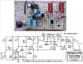
I have come across the following schematic, see below:

While I understand the higher level theory of the system and what it needs to achieve to transmit (modulation, demodulation). I don't understand why the specific components were placed as they are. From what I can see, L1 and VC1 are forming the tank circuit, but components such as C1, C2 and C3 I can't figure out what role they play. I would appreciate any insight into the design principles behind this circuit.
Thanks in advance!
I've been looking at building a simple FM transmitter to develop my understanding of wireless transmission - I find that's the best way to learn. Unfortunately, a lot of YouTube videos fail to analyze the circuit and just jump straight into putting the components together.
I have come across the following schematic, see below:
While I understand the higher level theory of the system and what it needs to achieve to transmit (modulation, demodulation). I don't understand why the specific components were placed as they are. From what I can see, L1 and VC1 are forming the tank circuit, but components such as C1, C2 and C3 I can't figure out what role they play. I would appreciate any insight into the design principles behind this circuit.
Thanks in advance!