Facebook
 Google
 GitHub
 Linkedin
HI friends
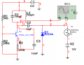
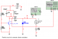
i draw a circui in multiism for production of a FM signal but not working
than k you in advance
George
i draw a circui in multiism for production of a FM signal but not working
than k you in advance
George
Attachments
-
 32.4 KB Views: 85