Flyback transformer gets too hot

Thread Starter

reza4872

Joined Sep 12, 2020
21
Hi
Hope you be well
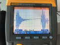
i have designed a flyback converter with specifications of Vout = 24v , Iout(max)=3A and Fs= 65KHz. when 40w load is connected to the output of the converter, transformer gets too hot in a short time. (about 85C in the room tempreture of 30C)
the core that i have used is EC28*28. i have inserted 1mm airgap on the middle leg of the core and i have used 3*0.4mm wire for primary and 2*.6 mm for the secendary winding. the inductance of the core is 300uH and the PWM controller is NCP1288
can anyone help me with my problem please
 

Ian0

Joined Aug 7, 2020
9,667
Is this an off-line flyback converter? So the input voltage is 325V (or half that in certain other parts of the world)?
What do you mean by the "inductance of the core"? Windings have inductance, not cores! What is the primary inductance?
How have you wound it? How many sections? Do you have the phase correct? Can your output diode withstand the voltage? Is the diode fast enough? What is its reverse recovery time? What MOSFET have you used? Apart from getting hot, does it deliver 40W @ 24V?
 
Last edited:

Ian0

Joined Aug 7, 2020
9,667
Filling the whole core with wire is generally counter-productive because of the proximity effect, (unless you have a multi-section winding) and anything above 0.5mm at that frequency is wasted because of the skin effect.

How about a photo of the transformer you have made?
 

Thread Starter

reza4872

Joined Sep 12, 2020
21
Can you tell if it is core loss or copper loss?
abou the amount of core loss i have no idea. but in a diferent test i connected the primary and secondary windings to dc vcurrent source with a constant 2A output. the copper loss was not a problem. windings were able to withstand the 2A current and temperature rise was nit significant
 

Thread Starter

reza4872

Joined Sep 12, 2020
21
Is this an off-line flyback converter? So the input voltage is 325V (or half that in certain other parts of the world)?
What do you mean by the "inductance of the core"? Windings have inductance, not cores! What is the primary inductance?
How have you wound it? How many sections? Do you have the phase correct? Can your output diode withstand the voltage? Is the diode fast enough? What is its reverse recovery time? What MOSFET have you used? Apart from getting hot, does it deliver 40W @ 24V?
Input voltage is 220v ac (rms value). the primary inductance of the transformer is 300uH. the output diode is BYV32-200 (ultrafast diode with max reverse recovery time of 35ns). Mosfet of the converter is SPA06N80. Phase of windings are correct and the converter is able to deliver stable output at 20w,36w,55w and no load condition.
i have used interleaved winding. 25turns (3strands of 0.4mm wire) foreach half of primary , 14turns (2 strands of 0.6mm wire) for secondary and 9 turns for auxiliary winding
 

Thread Starter

reza4872

Joined Sep 12, 2020
21
Filling the whole core with wire is generally counter-productive because of the proximity effect, (unless you have a multi-section winding) and anything above 0.5mm at that frequency is wasted because of the skin effect.

How about a photo of the transformer you have made?
i even have used another winding with 3strands of 0.25mm for primary and 3strands of 0.4mm wire for secondary. but the result is the same.
i have attached pictures of the converter and transformer
 

Attachments

Thread Starter

reza4872

Joined Sep 12, 2020
21
swicth snubber part of the I-ry ? // -- schematic
( ? the primary cap looks huge // -- but maybe it's normal for such power . . . ? would multiple smaller give less inductance )
sorry i did not understand the question you are asking?
 

Ian0

Joined Aug 7, 2020
9,667
300uH for entire primary
So, for 40W output, that is 615uJ per cycle
The energy stored is I^2L/2, so I(Pri)=2.025A
the reluctance is n^2/L = 8.33x10^6
the magnetomotive force = 101.3A
so the flux is 12.1uWb
and the flux density Is 141mT.
Seems like the magnetics design is sound.
It suggests an ON time of 1.8us - maybe a bit short.
What do the waveforms look like?
 

Thread Starter

reza4872

Joined Sep 12, 2020
21
So, for 40W output, that is 615uJ per cycle
The energy stored is I^2L/2, so I(Pri)=2.025A
the reluctance is n^2/L = 8.33x10^6
the magnetomotive force = 101.3A
so the flux is 12.1uWb
and the flux density Is 141mT.
Seems like the magnetics design is sound.
It suggests an ON time of 1.8us - maybe a bit short.
What do the waveforms look like?
i have attached Mosfet current (there is R_sense in series with it) and Voltage of drain- source
 

Attachments

DickCappels

Joined Aug 21, 2008
10,153
0.4 mm is much too large to be next to the core at 65 kHz. Many strands a finer magnet wire would create lower eddy current losses across the wire. You can make multistrand wire from regular enameled magnet wire with a twist per cm or so to help keep the wire tidy. A good starting point would be to use many strands of #30 or #32 to get the copper area you came up with earlier in the design.
 

Ian0

Joined Aug 7, 2020
9,667
Skin depth at 65kHz is 0.255mm, so 0.4mm wire seems OK to me.
I think you need more inductance (a smaller gap), because at the moment your transformer is only working Two-thirds of the time (all the time it isn’t ringing), meaning that current during that time is 50% greater than it need be. Or, alternatively, you could run the same transformer at 100kHz, but you’d need to change the IC.
The current waveform is messy. You need the earth probe attached directly to one end of the sense resistor to get an accurate waveform, not connected to some random circuit ground, and a shorter earth lead.
I’m a big fan of quasi resonant designs at that power level as it eliminates that dead time when the transformer isn’t doing anything. L6565 for example.
 
Top