Facebook
 Google
 GitHub
 Linkedin
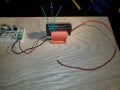
Hi, I'm new. And a novice. How do I wire in my flyback into my circuit?
This is my transformer: https://www.hv-experimental.com/image/cache/catalog/flyback_dc_wb-500x500.jpg
So I wrap 8 or 9 winds around the top of the core there. Then connect that primary wind to + and - from my circuit. 12V is pulsing through that.
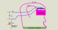
now where does my high voltage come from? The black wire is the negative and the main red wire in front there is the +? So the other red (the one with the black) goes no where? There are no pins on the bottom of the transformer. So my high voltage sparkgap is between the main red and black wires.. correct?
Also, this transformer is a DC flyback? Can these be used to light up a fluorescent tube? Or do I require an AC flyback transformer?
This is my transformer: https://www.hv-experimental.com/image/cache/catalog/flyback_dc_wb-500x500.jpg
So I wrap 8 or 9 winds around the top of the core there. Then connect that primary wind to + and - from my circuit. 12V is pulsing through that.
now where does my high voltage come from? The black wire is the negative and the main red wire in front there is the +? So the other red (the one with the black) goes no where? There are no pins on the bottom of the transformer. So my high voltage sparkgap is between the main red and black wires.. correct?
Also, this transformer is a DC flyback? Can these be used to light up a fluorescent tube? Or do I require an AC flyback transformer?
Attachments
-
 206.5 KB Views: 16
Last edited: