Facebook
 Google
 GitHub
 Linkedin
hi all,
I am new to this forum looking for some help. First of all, though I understand some of it, I am quite out of my depth on this one.
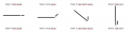
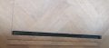
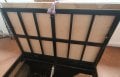
I have a hatch in my floor which is currently manually operated using a cleaning cloth (yes, I know). In order to operate it, first a small piece needs to be taken out of the way (as it will otherwise block the movement of the hatch), then the hatch can be opened using said cleaning clotch. See the pictures 1 and 2. When I installed the hatch, the plan was to use a linear actuator (12VDC, 1A) to raise/lower it. In order to operate it, an up/down switch was installed in my main light group (see picture 3).
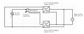
I've run into two issues I need to solve, where I am desperate for help. I've also attached my wiring diagram (apologies for any errors, not very good at it).
Issue 1:
The switch is only able to operate using 230V AC, whereas the actuator uses 12V DC. I've solved/jerryrigged this by wiring both the up and the down button to a separate power outlet. on each outlet, I use an AC adapter (for UP: 12VDC, 2A, for DOWN: 12VDC, 1.2A). When I connect either of the AC adapters to the actuator, everything works fine (in one direction). However, when I wire up both adapters (in opposite polarity to get both up and down movement), I do not have any movement (though some noise from the actuator). I believe I am shorting out the actuator.
How do I solve this?
I've looked at using single diodes, bridge rectifiers as well as a H-bridge, but my understanding of these are not good enough to implement a proper solution.
Issue 2:
I want to raise the small strip of wood out of the way using a servo motor prior to the main hatch moving. This I need to time that it moves before the main hatch rises on the UP movement and that it moves down again after the main hatch is lowered on the DOWN movement. For this I am considering a timed relay, but I am not sure how to wire these in this diagram.
Thanks for all the help, I really appreciated it! And all the best for 2022.
Marc
I am new to this forum looking for some help. First of all, though I understand some of it, I am quite out of my depth on this one.
I have a hatch in my floor which is currently manually operated using a cleaning cloth (yes, I know). In order to operate it, first a small piece needs to be taken out of the way (as it will otherwise block the movement of the hatch), then the hatch can be opened using said cleaning clotch. See the pictures 1 and 2. When I installed the hatch, the plan was to use a linear actuator (12VDC, 1A) to raise/lower it. In order to operate it, an up/down switch was installed in my main light group (see picture 3).
I've run into two issues I need to solve, where I am desperate for help. I've also attached my wiring diagram (apologies for any errors, not very good at it).
Issue 1:
The switch is only able to operate using 230V AC, whereas the actuator uses 12V DC. I've solved/jerryrigged this by wiring both the up and the down button to a separate power outlet. on each outlet, I use an AC adapter (for UP: 12VDC, 2A, for DOWN: 12VDC, 1.2A). When I connect either of the AC adapters to the actuator, everything works fine (in one direction). However, when I wire up both adapters (in opposite polarity to get both up and down movement), I do not have any movement (though some noise from the actuator). I believe I am shorting out the actuator.
How do I solve this?
I've looked at using single diodes, bridge rectifiers as well as a H-bridge, but my understanding of these are not good enough to implement a proper solution.
Issue 2:
I want to raise the small strip of wood out of the way using a servo motor prior to the main hatch moving. This I need to time that it moves before the main hatch rises on the UP movement and that it moves down again after the main hatch is lowered on the DOWN movement. For this I am considering a timed relay, but I am not sure how to wire these in this diagram.
Thanks for all the help, I really appreciated it! And all the best for 2022.
Marc
Attachments
-
 71.5 KB Views: 37
 -
 94.7 KB Views: 39
 -
 20.5 KB Views: 48
 -
 111.2 KB Views: 45

")