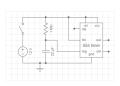
Flashing LED for 10 seconds using one 555 chip

WBahn

Joined Mar 31, 2012
33,321
That capacitor only charges once per operation, so its charge usage is negligible.
Possible, even probable. But it depends on how long he needs the battery to last (and just what battery is being used), as well as how often the circuit is activated. There's also the matter of leakage current, which generally increases with capacitor size. It sounds like the circuit will be unpowered most of the time, which mitigates this factor, but if there are times that it is powered for extended periods, that leakage current could add up pretty quickly. We simply don't have enough information to evaluate these things (or at least I don't, but they are things that the TS should be aware of. Since the TS seems to be concerned about parts count and, possibly, physical size, this might be being powered by something like an A27 12 V battery. Each cycle would remove about 4 mAs of charge. If he needs it to last a year and this is something that's going to get activated a few dozen times a day, then just charging that cap will deplete the battery. If it only gets activated once a day, then it would only account for about 2% of the capacity over a year.

Of course, I've assumed that it is battery powered (maybe carryover from another thread?) and I don't see where the TS has actually indicated how it is powered. If it's not, then this is a non-issue for this project, but still a consideration to be aware of for future projects.
 

WBahn

Joined Mar 31, 2012
33,321
12V is an absurd battery level if you ask me. Either it is 8 1.5V batteries or a power supply.
Why is it 8 1.5 V batteries instead of something like a single A27 or A23 battery, commonly used in remote controls, wireless doorbells, cigarette lighters, and quite a few other things?

The more relevant question is why 12 V in the first place? There is probably a more appropriate supply level, but we aren't given enough information to even guess.
 

74F00

Joined Oct 26, 2026
54
not necessarily... in a case like this MCU will need voltage regulator, which then will need in and out caps. then add R and C at reset pin... and still need resistor and LED. just saying that things do add up.
Try out PIC10F320. Its my personal favorite. Its one of the cheapest microcontrollers that you can put in a breadboard.
 

74F00

Joined Oct 26, 2026
54
I got it to be an 8 bit timer with shift registers for the inputs and outputs. One of my favorite parts is the puzzles in assembly! I know it also is the reason other people give up on it but it really is fun. (C is a bit too much for it) (I can show how I did it in more detail if anybody is wondering)
 

crutschow

Joined Mar 14, 2008
38,920
That depends on how often the user intends to power up the circuit.
Still will be very small compared to the total charge taken by the 555 and the LED during the 10 second flash interval, and the subsequent quiescent current if a bipolar 555 is used..
 
Last edited:

panic mode

Joined Oct 10, 2011
5,429
i have used MCUs for decades, and actively work of 4 projects right now that each use an MCUs. decade ago i was also using FPGA and did 60fps image compression (among other things). i think i know what MCUs and FPGAs can do. ;-)

but i also read TS post and see supply is 12V, yet several forum members are dismissing that for some reason. not that is impossible to put regulator inside MCU nut normally it is not there and normally supply voltage for MCU us 5V or less.
 
Top