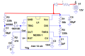
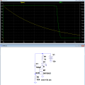
Flashing LED for 10 seconds using one 555 chip

crutschow

Joined Mar 14, 2008
38,932
Trying to find the minimum components that will fit in about 1 inch cube space in the cigarette adapter.
Doubt you will get much simpler than the 555 circuit in my post #8.
Circuit below with increased resistor values, to lower the capacitor values and thus make them physically somewhat smaller:
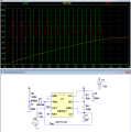
1793895918801.png

I may need to protect the circuit from voltage spikes using an automotive transient voltage suppressor (TVS) and a 47 ohm resistor so that will also take up some space. Not really sure if these will be needed or not.
Don't think you will see any damaging spikes in your application.
The large spikes noted in the literature are mainly from a load dump (sudden removal of the battery connection with the engine running) and that seldom happens.
But be sure and add the shown 68µF capacitor between the V+ and ground for filtering.
 
Last edited:
I have designed many automotive products.
People say a car voltage is 12V but that is not really true. When the engine is running it is more like 14.5V. When the engine is off the voltage can be anything from 0V to a little above 12V.
It is surprising how many times a battery gets put in backwards. We had a rool that everything me made had to survive a reverse battery via a diode or it needed to pop the replaceable fuse, without breaking any other parts.
On a low power product like this I would add a 10 ohm or 22 ohm resistor to help decouple C4 from the car's voltage. This will help with spikes.
1793892638552.png
 

Thread Starter

spiral8

Joined Aug 5, 2024
37
Here is my latest design. I decided to use a self-flashing LED to make the circuit as simple as possible. Also learned about MOSFETs and used one as it's better for the RC timing on the gate, than on the base of a bipolar transistor. I had to simulate a flashing LED since there's none in LTspice. I also had to simulate a 2N7000 MOSFET since it's also not listed in LTspice. ..... The car's voltage is shown as a 12 volt pulse that simulates starting the engine and turning it off. I did not try to simulate the varying car voltage due to engine cranking or alternator charging.

MOSFET led flasher 2548.jpg
 

crutschow

Joined Mar 14, 2008
38,932
If you connect the LED as shown in the sim below with C1 and R2 interchanged, then the MOSFET will initially turn on the blinking LED (not shown) and then
shut it off after the timeout.
This configuration also allows the use of a smaller capacitor for the desired timeout.

1793936092372.png
 

Thread Starter

spiral8

Joined Aug 5, 2024
37
If you connect the LED as shown in the sim below with C1 and R2 interchanged, then the MOSFET will initially turn on the blinking LED (not shown) and then
shut it off after the timeout.
This configuration also allows the use of a smaller capacitor for the desired timeout.

View attachment 373026
My first thought was doing it that way, with the MOSFET in series with the self-flash LED. But I wasn't sure if the MOSFET would work reliably with the self-flashing LED going to a near open circuit when dark. I'll put it is series per your suggestion.

BTW, with further Googling, I learned that a BS170 is similar to the 2N7000, is also in the TO-92 package and is a bit more robust. Plus the BS170 is listed in LTspice's NMOS list.
 

74F00

Joined Oct 26, 2026
58
In your first circuit:
1. What's the purpose of the 1K resistor across the 12 volts supply?
2. Can you give a step-by-step explanation of how the P and N mosfets oscillate and how they stop oscillating after 10 seconds? I'll try to figure it out but I'm not familiar with mosfet operation. Thanks.

In your second circuit:
1. I'm not sure that 555 will oscillate to flash the LED. Will try to figure that out.

EDIT:
After analysis, it appears to me that neither your circuit-1 or circuit-2 will oscillate and flash the led. Appears to me that both will turn the LED on solid and then turn it off. Please correct if I'm wrong. Thanks for posting.
1. The 1k resistor is so in my simulator the capacitor will discharge when I turn the circuit off. I assume that there will be other circuitry in your circuit so that probably will not be necessary.
2. Oh yeah they don't oscillate, I just made the circuit to turn on an LED for 10 seconds, I guess you might be able to connect that output to VCC of the 555 timer or to another place.

1. Yeah I misunderstood the post I thought it was just for an LED to be on for 10 seconds!

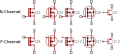
MOSFETs are like BJTs (which I assume you know) except they are dependent on the voltage across two pins. 51cc9e55ce395fea4b000000.png
So basically they measure the voltage between the gate (G) and the source (S) in P-Channel and if the SOURCE is a higher voltage then the drain (D) will be connected to the source. In my circuit I use a P-Channel MOSFET so when the capacitor is low it outputs high on the output. The N-channel is where you measure the voltage between the gate and the source and if the GATE is a higher voltage then the drain will be connected to the source. I hope that helps.
 

crutschow

Joined Mar 14, 2008
38,932
But I wasn't sure if the MOSFET would work reliably with the self-flashing LED going to a near open circuit when dark.
The MOSFET operation is unaffected by whether the LED is open or closed.
It's just acting as a switch.
I learned that a BS170 is similar to the 2N7000, is also in the TO-92 package
That should work also.
 
Last edited:

Thread Starter

spiral8

Joined Aug 5, 2024
37
1. The 1k resistor is so in my simulator the capacitor will discharge when I turn the circuit off. I assume that there will be other circuitry in your circuit so that probably will not be necessary.
Thanks for explaining use of the 1K resistor. In my car application, there will be many hours between use of the car when I'm at home, so that should give ample time for the timing cap to discharge. On the road, I'll already have my cell phone on me so proper operation of the circuit will be a non issue. Thanks.
 
Top