Flashing LED for 10 seconds using one 555 chip

Thread Starter

spiral8

Joined Aug 5, 2024
28
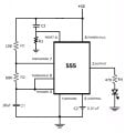
Will the following astable 555 circuit flash the LED for 10 seconds on power on and then stop flashing until power off?
Astable for car reminder 03.jpg
I'm hoping that reset pin-4 will go to about +12 volts on power on and gradually go low until it resets the 555 flip flop. Then output pin-3 will go low and stop flashing the LED until power off.

If it will work, what would the recommended values be for C3 and R3?

Do the other component values look OK for 1 second flashing?
 
Last edited:
Pin 4, /reset has a very wide range of voltage for the trip point. It will not be very predictable. Look at the data sheet for current on that pin. It is not high impedance. LM555. Pin-4 was not intended for good timing.

The TLC555 is a CMOS version where the current to drive pin-4 is very low. Your idea is more likely to work there. Still the input voltage is not accurate or predictable.

Many people would use two ICs to do this job. Or sometimes you can find a LED that includes a "blinker" inside.
 

WBahn

Joined Mar 31, 2012
33,321
Will the following astable 555 circuit flash the LED for 10 seconds on power on and then stop flashing until power off?
View attachment 372943
I'm hoping that reset pin-4 will go to about +12 volts on power on and gradually go low until it resets the 555 flip flop. Then output pin-3 will go low and stop flashing the LED until power off.

If it will work, what would the recommended values be for C3 and R3?

Do the other component values look OK for 1 second flashing?
On paper, the idea is okay. But in the real world you will find it's behavior will be pretty variable. For a given part, operating at a stable temperature, it might be repeatable enough for you to tweak it to get it close enough (which depends on how close is close enough for your needs).

I'd recommend using a 556 dual timer IC. Your external parts count will be about the same.
 

Thread Starter

spiral8

Joined Aug 5, 2024
28
Will the following astable 555 circuit flash the LED for 10 seconds on power on and then stop flashing until power off? ...snip...
Ron and WBahn,

Thanks for your replies.

The 10 second duration is very flexible. Just need enough flashing to act as a reminder when I power the circuit on. It could vary from 7 seconds to 13 seconds with no ill effects. Just for educational purpose, once C3 and R3 are selected, do you think that the on (flashing) time will be about the same on each power up?

The self-flash LED with a monostable 555 was my first thought but I already have normal LEDs in stock. A 556 chip would be another good idea. Trying to design a circuit with the absolute minimum amount of parts to do the job.
 

Thread Starter

spiral8

Joined Aug 5, 2024
28
Ron and WBahn,

Thanks for your replies.

The 10 second duration is very flexible. Just need enough flashing to act as a reminder when I power the circuit on. It could vary from 7 seconds to 13 seconds with no ill effects. Just for educational purpose, once C3 and R3 are selected, do you think that the on (flashing) time will be about the same on each power up?

The self-flash LED with a monostable 555 was my first thought but I already have normal LEDs in stock. A 556 chip would be another good idea. Trying to design a circuit with the absolute minimum amount of parts to do the job.
Dropping the rc circuit on pin-4 to act as a time delay. Because of your inputs, I googled it and response was that the leakage current on pin-4 would require R3 to be a low value like 1K. Then for a 10 second delay, C3 would have to be an enormous value like 3500 uf. No good.

Thanks for your input. Moving on.
 

AnalogKid

Joined Aug 1, 2013
12,289
Move the R3-C3 timer. Instead of driving the Reset input, connect it to the pins 2/6 node through a small signal diode.

R3 goes to Vcc. C3 goes to GND.

Diode anode goes to the R3/C3 node. Cathode goes to pins 2/6.

The circuit will oscillate until R3/C3 voltage is high enough to forward-bias the diode. Then R3 and R2 form a voltage divider. R3 must be smaller than R2 so the voltage at pin 2 is not low enough to trigger the 555 when the discharge pin is low.

Adjust R1-R2-C1 values to increase the network impedance by 10x - Increase the resistors and decrease C1. Select R3 to be about 1x to 1.5x R2. This will hold the trigger input to something greater than 1/3 Vcc when pin 7 is essentially at GND. Once you have R3, you can calculate C3 for 10 seconds.

The circuit will stop oscillating when the voltage across C3 reaches (2/3 Vcc + 0.6 V). This is approx. ((1.1 x R x C) x Vcc) + 0.6.

ak
 

crutschow

Joined Mar 14, 2008
38,920
do you think that the on (flashing) time will be about the same on each power up?
It shouldn't vary more than about ±1 pulse, as long as the power off time is sufficiently long to allow R3-C3 to fully discharge (>5 time-constants).
If you need it to recover faster then that, add another diode in parallel with R3 (cathode to V+), which will rapidly discharge C3 when the power goes to zero.

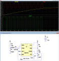
Below is the LTspice sim of AK's suggested modification to your circuit:
(For minimum parts count, C2 is likely not needed for this application.)

1793744675083.png
 
Last edited:

panic mode

Joined Oct 10, 2011
5,429
For the absolute minimum amount of parts it is hard to beat a MCU.
not necessarily... in a case like this MCU will need voltage regulator, which then will need in and out caps. then add R and C at reset pin... and still need resistor and LED. just saying that things do add up.
 

Thread Starter

spiral8

Joined Aug 5, 2024
28
Move the R3-C3 timer. Instead of driving the Reset input, connect it to the pins 2/6 node through a small signal diode.

R3 goes to Vcc. C3 goes to GND.

Diode anode goes to the R3/C3 node. Cathode goes to pins 2/6.

The circuit will oscillate until R3/C3 voltage is high enough to forward-bias the diode. Then R3 and R2 form a voltage divider. R3 must be smaller than R2 so the voltage at pin 2 is not low enough to trigger the 555 when the discharge pin is low.

Adjust R1-R2-C1 values to increase the network impedance by 10x - Increase the resistors and decrease C1. Select R3 to be about 1x to 1.5x R2. This will hold the trigger input to something greater than 1/3 Vcc when pin 7 is essentially at GND. Once you have R3, you can calculate C3 for 10 seconds.

The circuit will stop oscillating when the voltage across C3 reaches (2/3 Vcc + 0.6 V). This is approx. ((1.1 x R x C) x Vcc) + 0.6.

ak
Ha, ha. I like innovative thinking. Looks very nice. Thanks.
 

Thread Starter

spiral8

Joined Aug 5, 2024
28
It shouldn't vary more than about ±1 pulse, as long as on the power off time is sufficiently long to allow R3-C3 to fully discharge (>5 time-constants).
If you need it to recover faster then that, add another diode in parallel with R3 (cathode to V+), which will rapidly discharge C3 when the power goes off.

Below is the LTspice sim of AK's suggested modification to your circuit:
(For minimum parts count, C2 is likely not needed for this application.)

View attachment 372969
Thanks for taking the time to detail AK's suggestion. Excellent!
BTW, this is the first time I've heard of LTspice. Do you just upload a jpg drawing of the circuit for it to analyze? Hand drawn OK?
I wonder if LTspice would recognize the problem of putting the R/C circuit on the pin-4 reset that Google said was impractical?
 
Last edited:

ronsimpson

Joined Oct 7, 2019
4,857
not necessarily... in a case like this MCU will need voltage regulator, which then will need in and out caps. then add R and C at reset pin... and still need resistor and LED. just saying that things do add up.
The circuit could run from a 3V battery with no regulator. The MCU needs no crystal because many have a built-in oscillator. Probably there needs to be power supply 0.1uF cap and a resistor to limit the LED current.
 

WBahn

Joined Mar 31, 2012
33,321
Thanks for taking the time to detail AK's suggestion. Excellent!
BTW, this is the first time I've heard of LTspice. Do you just upload a jpg drawing of the circuit for it to analyze? Hand drawn OK?
I wonder if LTspice would recognize the problem of putting the R/C circuit on the pin-4 reset that Google said was impractical?
LTSpice is a circuit simulator. You create a netlist file that describes the circuit components and their connections (this is actually a text file) and each component has a device model associated with it (LTSpice comes with a library of hundreds of components and you can add more very easily). Most people create the netlist using a schematic capture program (LTSpice comes with one that isn't too bad).

It is a free program that you can download from Analog Devices (used to be Linear Technologies, hence the name). Just Google LTSpice and go to the link from analog.com. It installs pretty easily. There is a bit of a learning curve to it, but not bad for the basic suff.
 

crutschow

Joined Mar 14, 2008
38,920
BTW, this is the first time I've heard of LTspice. Do you just upload a jpg drawing of the circuit for it to analyze? Hand drawn OK?
Free download from Analog Devices.
No, it doesn't recognize a jpg or hand-drawn schematic.
It operates from a text-file netlist for the connections and part models, which is normally done with the built-in LTspice schematic capture function.

Netlist example from the LTspice schematic below:

1793745125011.png
I wonder if LTspice would recognize the problem of putting the R/C circuit on the pin-4 reset that Google said was impractical?
Yes, it generally would, but it depends upon the accuracy of the 555 model used in the simulation.

I have found many problems in my designs from their simulation before I actually built them.
 
Last edited:

WBahn

Joined Mar 31, 2012
33,321
330uF capacitors are not that big.
The TS was concerned about the size of his estiamted 3500 uF cap.

As to whether 330 uF is "not that big", that all depends on how much room he has available. Another factor could be how much charge it draws from the battery.
 

WBahn

Joined Mar 31, 2012
33,321
Ron and WBahn,

Thanks for your replies.

The 10 second duration is very flexible. Just need enough flashing to act as a reminder when I power the circuit on. It could vary from 7 seconds to 13 seconds with no ill effects. Just for educational purpose, once C3 and R3 are selected, do you think that the on (flashing) time will be about the same on each power up?

The self-flash LED with a monostable 555 was my first thought but I already have normal LEDs in stock. A 556 chip would be another good idea. Trying to design a circuit with the absolute minimum amount of parts to do the job.
A reminder for what? Usually, when I do something that I would like a reminded for, I don't really need to be reminded for just the ten seconds after I I've done something. It's later that I need the reminder. For instance, if this were something to remind me to close a gate that I've opened, it's not too likely that I will benefit from being reminded by a flashing LED (that I may or may not even see) during the ten seconds after I've opened the gate. If I didn't close it right after coming through it, I probably left it open for a reason and that reason is probably going to take longer than ten seconds and, if it does, then I'm no longer getting reminders when I need them, which is after I then go off and leave the gate open. So you might spend a bit of time asking yourself (1) is an LED really sufficient to act as a reminder (maybe you would better be served by an audible alert that gets your attention), and (2) what is the really relevant window that matters. For my gate example, I'd probably have it either start beeping every five seconds and keep beeping until I closed the gate, or have it not start beeping for a bit (maybe thirty seconds) to give me time to do most things that would have the gate open for while start beeping soon enough so that I probably haven't gotten far enough away to not hear it. How those considerations play out depend on the specific problem you are trying to solve, so just be sure that you've thought them through and not just latched onto the first thoughts that come to mind.
 
Top