 Facebook
 Google
 GitHub
 Linkedin
................................
06/29/18 SEE REVISED CODE AND WORD ATTACHMENT AT POST #4
This project has been discussed here: https://forum.allaboutcircuits.com/threads/sparkfun-4x20-lcd-redo.148031/
In brief, awhile back I bought the Sparkfun 4x20 LCD display (LCD-09568, https://www.sparkfun.com/products/9568 ) with a 1-wire interface good up to "38,400" baud .
It was finicky and locked up frequently. That problem is noted in several of the reviews.
SparkFun offered to refund my whole cost. However, when I noticed the display used the 18-pin PIC16F88 chip that is pin compatible with the 18-pin 16F1826/27 chips, I declined their kind offer and proceeded to develop a "fixed" LCD. Only two changes were made to the hardware.
First, a PIC16F1827 was substituted for the PIC16F88 MCU. It is important to use the 16F1827 instead of the very similar 16F1826, as the latter does not have PWM output on pin RA4. That output is required to have dimming control of the backlight. If you do not want the feature, the 16F1826 will work fine (cost about $1. 55).
Second, the crystal was changed from 10 MHz to 16 MHz. Most of my MCU projects are done with an oscillator at 4 MHz or doublings of that. The 16 MHz crystal allows the same baud rates for the display and MCU, and any error is of the same magnitude and direction.
Bill of materials:
PIC16F1827: Microchip PIC16F1827T-I/SO ($1.51 each)
16 MHz crystal: Abracon ABLS-16.000MHZ-B2-T ($0.30 each)
Attachments:
1) HD44780 Control Codes (Word document)
I kept to the standard Hitachi control codes. One or two of the LSB's of several coded are ignored. In a few cases, I reassigned those codes to other functions. Those codes are shaded in the Word document. Not all of the original Hitachi codes have been tested.
2) Schematic
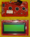
The schematic was reverse engineered from an actual SparkFun display. There are some parts of unknown function. I did not identify a pull-up resistor on MCLR (RA5) and set MCLR off in the configuration. RA4 (BL dim) also did not seem to have a pull-up resistor. A picture of the front and back of the modified SparkFun PCB is attached. The unmodified board looks similar.
3) Program Code
Assembly code is attached and was written using MPLab 8.92 IDE. As a note of caution, the default baud rate is set to 19200 (See: EEPROM initialization at the start of the code, DATAEE at 0xF000). When that baud rate is changed by the user, the new variables for the SPBRGH:L register pair are saved to the same EEPROM addresses. If you subsequently reprogram the chip, you must check "Preserve EEPROM" in the programmer settings menu (MPLab 8.92) if you do not want to revert back to the default 19200 baud.
Backlight dimming is achieved by using hardware PWM. Frequency is 500 Hz, and duty cycle is set by the value in register CCPR4L. Full on is attained by setting the duty cycle to zero, as that turns on the PNP control transistor (Q1). Off is attained by setting the PWM duty cycle to 100%. As noted before, there does not appear to be a pull-up resistor on that pin. The default setting for "dim" is 30% on.
Comments:
The display seemed stable and worked well to above 76800 baud. I did not determine a maximum baud, as I did not have a device to send a continuous stream of bytes. The best I could do was to send ascii codes using a series of "movlw 0xnn, call send byte" instructions with a transmitter MCU at 16 MHz. In order to minimize spacing delays, no loop was used. Reliable display of 30 characters was obtained with SPBRGL setting of 16 or greater (about 235,000 baud). Note, assuming 40 us per ascii character (per Hitachi datasheet), the theoretical maximum baud would be 250,000 baud (i.e., 1/(4X10^-5). Failures were noted with an SPBRGL value of 14 (about267,000 baud). I do not consider those observations of very high baud values reliable, as they probably are affected by pauses in my transmitter's data stream. At a baud rate of 115,200 (SPBRGL = 34), the display did seem stable, and that baud rate seems reasonably attainable (about 86 us per ascii characcter).
Copyright:
This material is copyrighted under the Creative Commons (https://creativecommons.org/licenses/ ) conditions for attribution and non-commercial use (Attribution-NonCommercial , CC BY-NC ). Portions of the code are from Mike McLaren (K8LH), and I believe he follows that same practice; although, I have not confirmed that with him.
Regards, John
06/29/18 SEE REVISED CODE AND WORD ATTACHMENT AT POST #4
This project has been discussed here: https://forum.allaboutcircuits.com/threads/sparkfun-4x20-lcd-redo.148031/
In brief, awhile back I bought the Sparkfun 4x20 LCD display (LCD-09568, https://www.sparkfun.com/products/9568 ) with a 1-wire interface good up to "38,400" baud .
It was finicky and locked up frequently. That problem is noted in several of the reviews.
SparkFun offered to refund my whole cost. However, when I noticed the display used the 18-pin PIC16F88 chip that is pin compatible with the 18-pin 16F1826/27 chips, I declined their kind offer and proceeded to develop a "fixed" LCD. Only two changes were made to the hardware.
First, a PIC16F1827 was substituted for the PIC16F88 MCU. It is important to use the 16F1827 instead of the very similar 16F1826, as the latter does not have PWM output on pin RA4. That output is required to have dimming control of the backlight. If you do not want the feature, the 16F1826 will work fine (cost about $1. 55).
Second, the crystal was changed from 10 MHz to 16 MHz. Most of my MCU projects are done with an oscillator at 4 MHz or doublings of that. The 16 MHz crystal allows the same baud rates for the display and MCU, and any error is of the same magnitude and direction.
Bill of materials:
PIC16F1827: Microchip PIC16F1827T-I/SO ($1.51 each)
16 MHz crystal: Abracon ABLS-16.000MHZ-B2-T ($0.30 each)
Attachments:
1) HD44780 Control Codes (Word document)
I kept to the standard Hitachi control codes. One or two of the LSB's of several coded are ignored. In a few cases, I reassigned those codes to other functions. Those codes are shaded in the Word document. Not all of the original Hitachi codes have been tested.
2) Schematic
The schematic was reverse engineered from an actual SparkFun display. There are some parts of unknown function. I did not identify a pull-up resistor on MCLR (RA5) and set MCLR off in the configuration. RA4 (BL dim) also did not seem to have a pull-up resistor. A picture of the front and back of the modified SparkFun PCB is attached. The unmodified board looks similar.
3) Program Code
Assembly code is attached and was written using MPLab 8.92 IDE. As a note of caution, the default baud rate is set to 19200 (See: EEPROM initialization at the start of the code, DATAEE at 0xF000). When that baud rate is changed by the user, the new variables for the SPBRGH:L register pair are saved to the same EEPROM addresses. If you subsequently reprogram the chip, you must check "Preserve EEPROM" in the programmer settings menu (MPLab 8.92) if you do not want to revert back to the default 19200 baud.
Backlight dimming is achieved by using hardware PWM. Frequency is 500 Hz, and duty cycle is set by the value in register CCPR4L. Full on is attained by setting the duty cycle to zero, as that turns on the PNP control transistor (Q1). Off is attained by setting the PWM duty cycle to 100%. As noted before, there does not appear to be a pull-up resistor on that pin. The default setting for "dim" is 30% on.
Comments:
The display seemed stable and worked well to above 76800 baud. I did not determine a maximum baud, as I did not have a device to send a continuous stream of bytes. The best I could do was to send ascii codes using a series of "movlw 0xnn, call send byte" instructions with a transmitter MCU at 16 MHz. In order to minimize spacing delays, no loop was used. Reliable display of 30 characters was obtained with SPBRGL setting of 16 or greater (about 235,000 baud). Note, assuming 40 us per ascii character (per Hitachi datasheet), the theoretical maximum baud would be 250,000 baud (i.e., 1/(4X10^-5). Failures were noted with an SPBRGL value of 14 (about267,000 baud). I do not consider those observations of very high baud values reliable, as they probably are affected by pauses in my transmitter's data stream. At a baud rate of 115,200 (SPBRGL = 34), the display did seem stable, and that baud rate seems reasonably attainable (about 86 us per ascii characcter).
Copyright:
This material is copyrighted under the Creative Commons (https://creativecommons.org/licenses/ ) conditions for attribution and non-commercial use (Attribution-NonCommercial , CC BY-NC ). Portions of the code are from Mike McLaren (K8LH), and I believe he follows that same practice; although, I have not confirmed that with him.
Regards, John
Attachments
-
68 KB Views: 27
-
15.4 KB Views: 31
-
30.5 KB Views: 32
-
 2.7 MB Views: 10
 -
2.7 MB Views: 19
Last edited:


