Facebook
 Google
 GitHub
 Linkedin
I have built an electric car for drag racing, and trying to create a field weakening circuit to improve performance at higher rpms. The car uses a DC series wound motor, so connections are available to put a resistive load across the field coils. The more common way to do this is to simply use a contactor to enable a resistor (shunt), or better, to make 3 or 4 'steps' using multiple contactors and shunts as RPMs continue to rise.
Adding shunt resistance in steps works well, but is a bit crude, and I believe that if a circuit could be made that provides a variable resistive load, that the effectiveness would be better than simple steps. Weakening could be started earlier and increase proportional to RPM. So a few controls would allow adjustment of min and max shunting, ramp rate, and timing of shunt activation. Timing would simply be a switch on the throttle that is only ON at full throttle. After a certain number of seconds at full throttle, the weakening circuit would begin it's work.
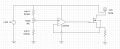
So I'm trying to put together a basic circuit using mosfets in their ohmic region, that would be controlled by an analog voltage input. The input would be controlled by a number of factors, but for test purposes a pot will provide the variable input.
The test circuit is low power proof of concept. The final circuit would have to shunt maybe 400-600A at up to 100V DC, but only for a 3-4 seconds.
Can mosfets be used in this way? Or is there a better device choice to create the variable resistive load?
Or can anyone point me at an existing circuit design for this purpose?
All suggestions appreciated!
Wayne Krauth
Adding shunt resistance in steps works well, but is a bit crude, and I believe that if a circuit could be made that provides a variable resistive load, that the effectiveness would be better than simple steps. Weakening could be started earlier and increase proportional to RPM. So a few controls would allow adjustment of min and max shunting, ramp rate, and timing of shunt activation. Timing would simply be a switch on the throttle that is only ON at full throttle. After a certain number of seconds at full throttle, the weakening circuit would begin it's work.
So I'm trying to put together a basic circuit using mosfets in their ohmic region, that would be controlled by an analog voltage input. The input would be controlled by a number of factors, but for test purposes a pot will provide the variable input.
The test circuit is low power proof of concept. The final circuit would have to shunt maybe 400-600A at up to 100V DC, but only for a 3-4 seconds.
Can mosfets be used in this way? Or is there a better device choice to create the variable resistive load?
Or can anyone point me at an existing circuit design for this purpose?
All suggestions appreciated!
Wayne Krauth