Failing to enable Relay with Standalone Atmega328p

Thread Starter

mukund_bm

Joined Aug 24, 2014
21
Dear Friends,

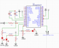
Attached the schematic, I have designed Atmega329P as standalone system. The Atmega328 programming / debugging is configured using Arduino Uno using Tx, Rx, Reset and Gnd. This is working perfectly right.

Whenever I disconnect Arduino Uno, Ralay failed to start. Kindly guide how to proceed further.
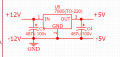
1605950363576.png
Supply Regulator
1605950499134.png
 

Attachments

DickCappels

Joined Aug 21, 2008
10,153
What kind of drive does your relay need in terms of volts and amps across and through the solenoid? Is there a driver on the relay module?

You need to add an electrolytic capacitor (about 10 uf or more) and a ceramic capacitor (about .01 uf) in parallel across the power supply pins to assure reliable operation, especially when driving and inductive load.

A 10k pull-up resistor to hold the reset input high is a good idea. The internal pullup on the reset pin is high resistance and sometimes a capacitor to ground in needed, especially when driving an inductive load.
 

KeithWalker

Joined Jul 10, 2017
3,063
As Dick mentioned, the reset pin should be connected to +5V through a 10K resistor.
You also need to connect the junction of C3 and C6 to the ATMega328 GND for a reliable external clock.
D6, D7 and D8 should not be connected to +5V as shown in the diagram. If they are activated LOW the pins will be damaged.
I am assuming that you used an Arduino Uno to load the bootloader onto the ATmega328. How are you loading the program after that? Can you show a listing of your program?
Have you tried loading and running the "Blink" program while measuring the voltage on pin 19? That is the first thing I do after I have loaded the bootloader onto a fresh ATmege328, just to make sure everything is working.
Regards,
Keith
 
Last edited:

MrChips

Joined Oct 2, 2009
30,708
Connections at D6, D7, D8 don't look right. If any one of these is configured as a low output then you are creating a short across the power supply that might kill the MCU.
 

Thread Starter

mukund_bm

Joined Aug 24, 2014
21
Thanks Mr. Dick and Mr. Keith, after adding the electrolytic capacitor (about 10 uf or more) and a ceramic capacitor (about .01 uf) in parallel and 10k Pull-up resistor the issue is resolved.

Thank you very much for providing guidelines...
 
Top