We can't tell were you are getting stuck in your attempt to derive them unless you show us your attempt to derive them.
Draw the circuit, set up the equation for what you want to determine, and then do your best to get those results. Show all of that and then we have something to work with in order to help you get where you are trying to get.
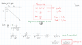
Here was my terrible attempt.
I was told that this was wrong and had to Re-do it. I don't really know what else to do :/
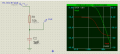
Also, i did the circuit on proteus with a frequency response graph. Green is Gain and red is Phase. My goal was to derive the graph.
Although, in looking things over, it doesn't appear too terrible at all.
But you appear to have gotten the answer you were looking for as far as the magnitude of the gain goes -- although it is a bit by coincidence -- and you haven't shown any work for the phase part.
The first thing that is missing from your attempt is the circuit you are trying to analyze. The reader (whether it be me or the grader) shouldn't have to guess. In this case, I had to look over at your simulation and assume (probably safe to do so) that that was the circuit you were analyzing. In general, your work should be self-contained. Get in the habit of doing that and it will pay big dividends, both now in school and later in the real world.
Conceptually you are making a mistake in your initial set up. It's true that the gain is defined at Vout/Vin, but the gain thus defined in a complex quantity. You immediately mixed a complex voltage in the numerator with a magnitude in the denominator. It didn't bite you this time, but it will with more complex circuits. So either work with the complex expressions for the voltage or set up the equation for the magnitude of the gain, which is
You made a couple of mistakes, although one of them appears to be just sloppy notation. At one point you squared the top and bottom, but you continued to set things equal. At the end you remembered to take the square root, but only because you mentally kept track of the need to do it. In essence, you claimed that x/y = x²/y², which is not true. Get in the habit of keeping your work mathematically clean. If you don't, then the sloppiness will eventually bite you big time because, as things get more complicated, it will become impossible to keep things straight in your head well enough to undo the sloppiness later.
The mathematical mistake you made is that when you squared -j you got -j² and then said that this is +1. But it is (-j)² = (-1)²j² = -1.
This won't affect the magnitude part of the solution, but it will affect the phase; since you haven't shown any work for that part, I can't tell if this is where you are getting tripped up or not.
Here was my terrible attempt.
I was told that this was wrong and had to Re-do it. I don't really know what else to do :/
Also, i did the circuit on proteus with a frequency response graph. Green is Gain and red is Phase. My goal was to derive the graph.
 Facebook
 Google
 GitHub
 Linkedin
 28.1 KB Views: 18