Explanation on breadboard LED short

Thread Starter

ghulen

Joined Jan 4, 2018
14
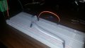
Is this LED shorted because the orange wire has less resistance compared to the LED? Meaning the current skips the LED and goes straight to the orange wire, completing the circuit. Or am I way off here?
 

Attachments

BobTPH

Joined Jun 5, 2013
11,515
No, it is shorted because both leads are going into the same row of holes in the breadboard, which are all connected together.

Bob
 

paulktreg

Joined Jun 2, 2008
851
To further elaborate on Bobs post the row of five connection points you have your battery positive, LED and resistor connected to are all connected together on row 38. All the rows of five connection points either side of the mid line point are connected together so all you have is the resistor wired across the battery.
 

Thread Starter

ghulen

Joined Jan 4, 2018
14
To further elaborate on Bobs post the row of five connection points you have your battery positive, LED and resistor connected to are all connected together on row 38. All the rows of five connection points either side of the mid line point are connected together so all you have is the resistor wired across the battery.
Thank you for further elaborating. Im obviously new, so I still dont quit understand. The issue is having both positive and negative leads of the LED hooked up to the same thing?
 

spinnaker

Joined Oct 29, 2009
7,830
Thank you for further elaborating. Im obviously new, so I still dont quit understand. The issue is having both positive and negative leads of the LED hooked up to the same thing?

You need to turn the resistor the LED in the other direction. On a breadboard those wider strips have the rows all connected together. The power bus (the thin ones) the column is all connected together
 

Thread Starter

ghulen

Joined Jan 4, 2018
14
You need to turn the resistor the LED in the other direction. On a breadboard those wider strips have the rows all connected together. The power bus (the thin ones) the column is all connected together
I have already turned those, and got it to work. I know the layout of the breadboard, but i just cant understand why the LED is shorted, even with everyone's explanation.
 

AnalogKid

Joined Aug 1, 2013
12,130
The LED is shorted because its two leads are connected directly together. That is a good working definition of a dead short. If you really do know the layout of the breadboard, how can there be a question here.

If you wedged the steel blade of a screw driver between the two LED pins, that would be a dead short between the pins. Because both LED pins are in the same strip, the breadboard is doing the same thing.

ak
 

AnalogKid

Joined Aug 1, 2013
12,130
Is this LED shorted because the orange wire has less resistance compared to the LED?
No, it is because the plated steel contacts in the breadboard have less resistance than the LED. The orange wire has nothing to do with whether or not the LED pins are shorted.

Rotate the LED 90 degrees, so that one pin is in row 38 and the other pin is in row 36. Move the Orange wire from row 38 to row 36. The LED should light now. If it doesn't, reverse its pin connections.

ak
 

spinnaker

Joined Oct 29, 2009
7,830
I have already turned those, and got it to work. I know the layout of the breadboard, but i just cant understand why the LED is shorted, even with everyone's explanation.

How can the LED be working if it is shorted???

What makes you think it is shorted?
 

Thread Starter

ghulen

Joined Jan 4, 2018
14
How can the LED be working if it is shorted???

What makes you think it is shorted?
The LED isnt working in this picture. I did however make a successful circuit later on that would light the LED. I was just trying to grasp why the setup in the provided picture wouldnt work. I just need to read more about a dead short
 

Thread Starter

ghulen

Joined Jan 4, 2018
14
The LED is shorted because its two leads are connected directly together. That is a good working definition of a dead short. If you really do know the layout of the breadboard, how can there be a question here.

If you wedged the steel blade of a screw driver between the two LED pins, that would be a dead short between the pins. Because both LED pins are in the same strip, the breadboard is doing the same thing.

ak
I need to read more about short circuits. Im fairly new, so any recommended books or youtube videos would be great.
 

ebeowulf17

Joined Aug 12, 2014
3,307
For the LED to light up, current must flow through it. This is a dramatic oversimplification, but you could imagine electricity is like water, in the sense that it takes the path of least resistance (in reality, it sort of takes every available path, but with more current flowing where there's less resistance and vice versa.)

A dead short basically refers to a path with very, very low resistance. The row in the breadboard has really low resistance. Plugging things into its 5 holes is basically like touching them all to the same wire.

Obviously it's "easier" for the current to flow through the row (basically a wire) than for it to flow through the LED, so essentially all of the current goes through the row, not through the LED.
 

spinnaker

Joined Oct 29, 2009
7,830
I need to read more about short circuits. Im fairly new, so any recommended books or youtube videos would be great.
The LED isnt working in this picture. I did however make a successful circuit later on that would light the LED. I was just trying to grasp why the setup in the provided picture wouldnt work. I just need to read more about a dead short
You don't know what a short is??? A wire connected together is a short. Current chooses the path of least resistance. If you have a short across the LED, the current will flow through the wire and not the LED because the LED has a higher resistance that the wire. Because it is a diode it is really more complicated than that but for now you can think of it as a higher resistance.
 

Thread Starter

ghulen

Joined Jan 4, 2018
14
For the LED to light up, current must flow through it. This is a dramatic oversimplification, but you could imagine electricity is like water, in the sense that it takes the path of least resistance (in reality, it sort of takes every available path, but with more current flowing where there's less resistance and vice versa.)

A dead short basically refers to a path with very, very low resistance. The row in the breadboard has really low resistance. Plugging things into its 5 holes is basically like touching them all to the same wire.

Obviously it's "easier" for the current to flow through the row (basically a wire) than for it to flow through the LED, so essentially all of the current goes through the row, not through the LED.
Thank You!! That last part exactly what I was looking for, and now I understand! thank you
 
Top