Facebook
 Google
 GitHub
 Linkedin
Thank you very much for your answer.
I just tried connecting pins with the old firmware installed. Without result......
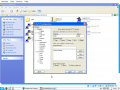
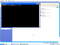
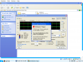
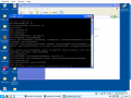
Just a short deviation from the discussion's line:http://www.allaboutcircuits.com/projects/update-the-firmware-in-your-esp8266-wi-fi-module/
A start over with attempts following the steps described in link.
I just tried connecting pins with the old firmware installed. Without result......
Just a short deviation from the discussion's line:http://www.allaboutcircuits.com/projects/update-the-firmware-in-your-esp8266-wi-fi-module/
A start over with attempts following the steps described in link.