 Facebook
 Google
 GitHub
 Linkedin
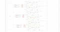
Yep disconnected completed nothing on the diode of the opto. I've made an updated circuit in case that helps the diagrams are represented in a weird way:Did you completely disconnect the diode of the opto?
yes that's correct it's that operational amplifierI think it is TSV621
http://www.st.com/en/amplifiers-and-comparators/tsv621.html
Attachments
-
 689.6 KB Views: 7
Last edited:


