 Facebook
 Google
 GitHub
 Linkedin
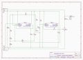
At the moment I get these frequency variations without the motor connected.The timing of a 555 depends on both component values and supply voltage, and the triggering also depends on a stable voltage. A large filter capacitor across the IC supply, and usin a regulated supply for the timer will help. Any voltage noise can have an effect on the triggering, and so it is useful to have a separate power feed for the timer.
On the circuit board, since there are multi-pin power connectors already, I suggest separate pins and traces for the motor power circuit. Even the best DC motors create some power circuit noise that can affect other parts of the system. The connections to C1 seem to be sharing a current path with other elements, but not having the circuit visible now that may not be an issue.
I do suggest making the negative common trace as wide as is reasonable since lower ground impedance reduces unintended coupling.
C1 connects to the circuit as attached but the line from the emitter of the power transistor to GND runs underneath it.
Do you also mean I should put a 10uf cap across pins 1&8 of both ICs?
Attachments
-
 349.6 KB Views: 8


