Facebook
 Google
 GitHub
 Linkedin

I was able to get started with the problem with the previous exercises i have done, i am struck up at one point
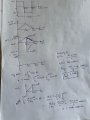
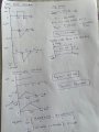
During ON time when the transistor is ON
The inductor equation is V = L di/dt;
V = 12V; L = 75mH; t = 20ms
iL = 12*20*10^-3/75*10^-3 Amps = 3.2A;
when the transistor is OFF
The current has to be continuous, so the inductor voltage has to change to maintain that current. I am unable to find this voltage, if i attempt
use the KVL equation
Vcc - VL - Vz = 0;
VL = Vcc - Vz
(Vcc - Vz) = 75*10^-3 * 3.2/50*10^-3;
I get Vz = 7.2V but the zener diode is not reverse biased, I am struck up here.


")