Encoder signal through a very long wire

Thread Starter

cmartinez

Joined Jan 17, 2007
8,218
Start a new thread. Include the datasheet in the post. Make it a new discussion.
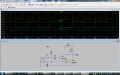
Ok, here's the encoder's datasheet. And here's my question: Would the following adaptation of your circuit (no cap this time, for your great relief...), as shown in the figure below, be adequate to receive the signal from that encoder through a shielded wire 20m long, assuming that the frequency remains below 100 Khz?

Capture.JPG

Would a value for R3 of 4.7k be acceptable if the signal is a square wave of 0 to 5V, push-pull, 4ma max?

Note: In my application, direction of rotation is not important, so I plan to XOR the encoder's two quadrature outputs to obtain a single square wave. As shown in the attached simulation.


@ronv, @ian field, @RichardO, @strantor, @AnalogKid, @blocco a spirale
 

Attachments

Thread Starter

cmartinez

Joined Jan 17, 2007
8,218
Correction: By using the xor circuit in the previous post, the signal would be limited to 0.5 mA, so maybe I should change R3 (in the sim) from 10K to 1K to obtain an output of 5mA?
 

AnalogKid

Joined Aug 1, 2013
10,986
Which output(s) are you using? The datasheet recommends a min value for your R3 of approx. 10K (2 x 4.7K) "to prevent loading" of the PWM output.

ak
 

Thread Starter

cmartinez

Joined Jan 17, 2007
8,218
Which output(s) are you using? The datasheet recommends a min value for your R3 of approx. 10K (2 x 4.7K) "to prevent loading" of the PWM output.

ak
Thanks, I'll only be using the outputs of channels A and B (pins 3 and 4) connected to the xor gate that I just mentioned. This to minimize the number of wires and additional programming, since I won't need to know direction of rotation in my application.
My intention is to track position, not speed, so I won't be using the PWM output at all.
 

joeyd999

Joined Jun 6, 2011
5,234
Really, you're going to make me read the whole data sheet?

First, if you xor you're going to have problems with noise at transition points.

Second, does this chip operate stand-alone? Or does it require an associated mpu for programming?

Third, no...my circuit is not applicable -- and I take no responsibility for your use of it. For short runs, properly grounded shielded wire will be preferable, and maybe with a decent interface IC/buffer/receiver. For longer runs/higher speeds, you'll need to consider rise and fall times, and reflections (transmission line effects).

Other than this, I have no opinions -- and will not have without studying the datasheet further, which I have no inclination to do. Good luck. We are all counting on you.
 

Thread Starter

cmartinez

Joined Jan 17, 2007
8,218
Really, you're going to make me read the whole data sheet?

First, if you xor you're going to have problems with noise at transition points.

Second, does this chip operate stand-alone? Or does it require an associated mpu for programming?

Third, no...my circuit is not applicable -- and I take no responsibility for your use of it. For short runs, properly grounded shielded wire will be preferable, and maybe with a decent interface IC/buffer/receiver. For longer runs/higher speeds, you'll need to consider rise and fall times, and reflections (transmission line effects).

Other than this, I have no opinions -- and will not have without studying the datasheet further, which I have no inclination to do. Good luck. We are all counting on you.
I'll do my homework Joey, I promise you that. And NO... I never expected you to read the whole thing, that would've been rude of me.

The datasheet states that its A and B channels are digital outputs able to deliver up to 4 mA. I'm guessing they mean they are the push-pull type, since some other pins (that will remain unused) have an open drain configuration.
About your second point: The chip is stand alone and I'll be running it at 5V, although it can be reprogrammed to perform different functions that I'm not going to need in my application.
And as for your third point, thank you for clarifying... I'm now examining the possibility of converting the output signal into a differential one... possibly by using an RS485 chip... though I'll also have to consider the chip's max frequency, proper line termination and all those details needed to minimize the effects that you've just mentioned.
 

kubeek

Joined Sep 20, 2005
5,794
Note: In my application, direction of rotation is not important, so I plan to XOR the encoder's two quadrature outputs to obtain a single square wave. As shown in the attached simulation.
If you just need step pulses, then I suggest you reprogram the thing for mode 2 instead of using XOR.

I don´t really think that differential is necessary here, but sure it wouldn´t hurt to use some buffering of the 4 mA outputs. Or maybe using a current loop, but i am not too sure how much better those are at fignting induced noise.

All said, i feel that using a 74HC125 or 126 as a buffer feeding a twisted pair line should be enough.
 

Thread Starter

cmartinez

Joined Jan 17, 2007
8,218
I suggest you reprogram the thing for mode 2 instead of using XOR.
Yeah, I had thought about that, but it requires writing extra code and the use of a 7.4V regulated supply and a transistor interface to the MCU... I think it's easier to just xor the outputs. As for using an HC buffer for this purpose, thanks for your suggestion, I'll consider it among the other options.
 

Papabravo

Joined Feb 24, 2006
21,159
You need A, B, and GND since the signals from the chip are referenced to the chip ground. You are going to have problems with the GND difference between the two systems especially if the encoder is getting it's power from a different place than the receiver. The 20 M of cable is going to look like a big capacitor to the encoder and 4 mA may not be enough to charge and discharge that much cable. Using a CMOS device with symmetrical output stages (sources as much current as it can sink) is a plus. You can test the efficacy by running a square wave of a given frequency through 20M of cable and observe the resulting waveforms,
 

kubeek

Joined Sep 20, 2005
5,794
You need A, B, and GND since the signals from the chip are referenced to the chip ground. You are going to have problems with the GND difference between the two systems especially if the encoder is getting it's power from a different place than the receiver...
But since the power is already present at the decoder I suggest doing the XOR there, it will make all things much simpler.
 

kubeek

Joined Sep 20, 2005
5,794
Yeah, I had thought about that, but it requires writing extra code and the use of a 7.4V regulated supply and a transistor interface to the MCU... I think it's easier to just xor the outputs. As for using an HC buffer for this purpose, thanks for your suggestion, I'll consider it among the other options.
I think the datasheet say the chip is one time programabble, so you need to set this only once. Of course what you would choose depends if this is a one off project, or if you are planning to make loads of them.
 

Thread Starter

cmartinez

Joined Jan 17, 2007
8,218
But since the power is already present at the decoder I suggest doing the XOR there, it will make all things much simpler.
So you're suggesting I use a 4 wire shielded cable for this? One for +5V into the encoder, another one for ground, one for channel A, and another one for B. Use a 74HC125 buffer at the encoder side and receive at at the MCU using the circuit shown in post #1 ?.
 

Thread Starter

cmartinez

Joined Jan 17, 2007
8,218
Don't forget these guys

http://www.onsemi.com/pub_link/Collateral/MC26LS30-D.PDF
http://www.ti.com/lit/ds/symlink/am26c32-ep.pdf

Also -- consider using a Schmitt-Trigger on the receiver input.
What about using a MAX488? I have quite a few of them laying around... they might just do the trick if I were to send +12V power through one of the wires, then at the encoder side bring it down and regulate it with a 7805, then XOR the encoder's outputs and send the signal back to the MCU's board through the differential lines, where another MAX488 would translate its level back to a 5V waveform.

I'd still be using a 4 wire shielded cable:
  1. +12VDC
  2. GND
  3. Y output \ (see fig 2 in pg 8 of the datasheet)
  4. Z output /
 

Attachments

Last edited:

kubeek

Joined Sep 20, 2005
5,794
If you already got those then definitely go with them. Even though you need 12V instead of 5V, and you will need to regulate that at the encoder side to 5V, it is by far the best way to get data over a long wire. An STP or F/STP ethernet cable would probably be the optimal solution. I would use one pair for data and one pair for Ground and Vcc. As the cable usally has four pairs this would still leave you enough room to expand to detecting the direction if needed.
 
Top