Converting a high-low signal to an ABZ encoder output using FPGA?

Thread Starter

HighVoltageJoe

Joined Jun 1, 2017
36
Hi,

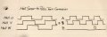
I am considering the use of an FPGA to convert a UVW 60 degree out-of-phase digital signal coming from a hall sensor on a linear motor to an incremental ABZ signal output to feed into a variable frequency drive for positioning. The problem with this is that I have never used an FPGA before and don't even know where to start. To be 100% honest, they seem overwhelming to me but seem to be the only solution to my problem. I have read the FPGA for dummies and am still lost.

Would anyone be willing to have a 1-on-1 conversation with me about FPGAs or help me figure out if the FPGA is the right choice for my application?

All the best,
Joe M
 

MaxHeadRoom

Joined Jul 18, 2013
28,576
The commutation of hall sensors in a BLDC motor etc are very coarse if intended to reproduce a ABZ (incremental?) encoder.
What do you intend to do with them?
Max.
 

Thread Starter

HighVoltageJoe

Joined Jun 1, 2017
36
The commutation of hall sensors in a BLDC motor etc are very coarse if intended to reproduce a ABZ (incremental?) encoder.
What do you intend to do with them?
Max.
the motors are linear so they are non-rotational. I want to take the signals from each hall sensor (these hall sensors are placed on the motor such that the signals that it creates are each 60 degrees out of phase from one another) and make them imitate an encoder signal. I want to then feed this encoder signal into the variable frequency drive that is driving the motors for positioning...
 

MaxHeadRoom

Joined Jul 18, 2013
28,576
What resolution are you going to end up with?
Typical incremental encoders, the two pulses are at 90° to each other, (quadrature).
Max.
 

Thread Starter

HighVoltageJoe

Joined Jun 1, 2017
36
What resolution are you going to end up with?
Typical incremental encoders, the two pulses are at 90° to each other, (quadrature).
Max.
Yes I want a quadrature signal out but I'll be feeding it 3 hall signals in (each 60 degrees apart). I don't need that great of resolution, just something lol. Thank you for your help by the way, I really appreciate it!
 

MaxHeadRoom

Joined Jul 18, 2013
28,576
I don't quite see how you are going to end up with any usable signal with a fine enough resolution when using hall sensors to produce a 90° signal.?
Max.
 

tsan

Joined Sep 6, 2014
138
I guess this is a hobby project, otherwise a position sensor suitable for VFD would be used. Anyway, have you tried connecting two 60 degree out-of-phase digital signals to VFD as AB signals? This assumes, that the digital signal is correct level for the VFD. VFD counts channel A and B pulses and it is possible that it doesn't care that the phase difference is 60 degrees instead of 90. Signal quality should be good to avoid wrong position, because there is no zero pulse or perhaps zeroing the position could be done with a limit switch on some part of the movement sequence.
 

Thread Starter

HighVoltageJoe

Joined Jun 1, 2017
36
I don't quite see how you are going to end up with any usable signal with a fine enough resolution when using hall sensors to produce a 90° signal.?
Max.
I guess this is a hobby project, otherwise a position sensor suitable for VFD would be used. Anyway, have you tried connecting two 60 degree out-of-phase digital signals to VFD as AB signals? This assumes, that the digital signal is correct level for the VFD. VFD counts channel A and B pulses and it is possible that it doesn't care that the phase difference is 60 degrees instead of 90. Signal quality should be good to avoid wrong position, because there is no zero pulse or perhaps zeroing the position could be done with a limit switch on some part of the movement sequence.
I have not tried connecting two of the hall signals to the drive. I am mainly just interested in what I get on the output more than anything. I mainly just want to use this as a reason to start using FPGAs lol. I just don't know how to go about it is all.
 

panic mode

Joined Oct 10, 2011
2,703
learning FPGA is a bit unusual as programin language describes hardware. it takes some getting used to.
like with everything, you need to take small steps. if you are doing it on your own make sure to get development board that is popular or you will be likely more or less on your own. you don't want to fight on many fronts so avoid ideas of getting some discount deal that needs some tinkering to get it to run. go for the ready to use product with good support base. dealing with VHDL is enough without having to vory about zillion other things that can go wrong.
 

panic mode

Joined Oct 10, 2011
2,703
and about your signal conversion - draw the signals as good as you can and explain what you wish to do. then we can talk. quadrature signals are 90deg... but don't have to be. even if the phase shift is 5 or 0.5 degrees, this can work if your hardware is fast enough (or signal is slow enough). making it 90deg simply gives you the most tolerance for fast changes.
if your UVW signals are digital and 60frg appart, are they still 50% duty? this will have an effect on how to tackle the problem.

for example, if things ar on your side, pair of OR gates may be all that is needed. no programming required:
A=U OR V
B=V OR W
Z may not be needed or can be based on counter.
 

Thread Starter

HighVoltageJoe

Joined Jun 1, 2017
36
and about your signal conversion - draw the signals as good as you can and explain what you wish to do. then we can talk. quadrature signals are 90deg... but don't have to be. even if the phase shift is 5 or 0.5 degrees, this can work if your hardware is fast enough (or signal is slow enough). making it 90deg simply gives you the most tolerance for fast changes.
if your UVW signals are digital and 60frg appart, are they still 50% duty? this will have an effect on how to tackle the problem.

for example, if things ar on your side, pair of OR gates may be all that is needed. no programming required:
A=U OR V
B=V OR W
Z may not be needed or can be based on counter.
I have attached a picture of the signals that I want to go in and what I want to come out. I will get some more info tomorrow about the signals that I have and let you know. I can use a FPGA to set that up correct if that is indeed the way I need to go? I have one on the way and it would make sense for me to use it. All I'd have to do is set the wires up to make each gate an OR gate correct? I'm still learning about these, so that is why I am asking.

Thank you for your response,
Joe M


EDIT: As I began thinking about this a little more, I would need more than two OR gates because as my motor goes from U-V-W, it has to output a low signal somewhere in the middle or else it would be constantly high.
 

Attachments

Last edited:

panic mode

Joined Oct 10, 2011
2,703
UVW gives you 6 unique states per motor revolution. this may be sufficient in some cases but normally it is too crude - tipically servo motor is coupled with encoder that gives it thousands of pulses/states per motor revolution. and yes... since motor can be stopped in any position, encoder signals could be high or low. this is by design...
 

MaxHeadRoom

Joined Jul 18, 2013
28,576
At one time a resolver was popular for rotary positioning due to its rugged construction, but due to the fact it is very low resolution, the sine-cosine signals were used for cotangent calculation was used in order to detect positioning with a much finer resolution. Approaching the resolution of low end quadrature encoders.
Max.
 

Thread Starter

HighVoltageJoe

Joined Jun 1, 2017
36
UVW gives you 6 unique states per motor revolution. this may be sufficient in some cases but normally it is too crude - tipically servo motor is coupled with encoder that gives it thousands of pulses/states per motor revolution. and yes... since motor can be stopped in any position, encoder signals could be high or low. this is by design...
Correct. That is what I am trying to do with the FPGA...figure out if it will be a sufficient way to do what I want to do. I just do not know the steps I have to go through to do the programming. I've been sitting, trying to figure out what array of logic gates that I need to keep chaining together to get my desired output. I am completely lost, but I want to learn. I would like to get a quadrature signal out from those three input signals that I have. And sorry if the vocabulary that I am using is rather unprofessional, I am still a senior in high school so bear with me lol!

Thanks and stay safe,
Joe
 

Thread Starter

HighVoltageJoe

Joined Jun 1, 2017
36
At one time a resolver was popular for rotary positioning due to its rugged construction, but due to the fact it is very low resolution, the sine-cosine signals were used for cotangent calculation was used in order to detect positioning with a much finer resolution. Approaching the resolution of low end quadrature encoders.
Max.
Hmmmmm...never heard of one of those. I'll have to do some research on their signal processing to see if any of it is similar to what I am trying to do.

Thanks and stay safe,
Joe
 

MaxHeadRoom

Joined Jul 18, 2013
28,576
quadrature signal out from those three input signals that I have.
Joe
Typically quadrature detection uses 2 sine or square wave signals that are space 90° apart.
Original use in a positioning encoder used one signal for rate the other direction, it eventually developed into using all 4 edges of the two square wave signals to indicate both direction and 1x, 2x, or 4x the natural pulse frequency.
To detect different resolutions.
Max.
 
Top