Converting low current 24VAC to high current 24VAC for legacy sprinkler system

Thread Starter

DS2068

Joined Aug 30, 2017
5
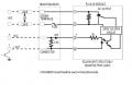
I'm a bit embarrassed to ask this since it should be trivial. I'm trying to use a modern sprinkler controller (Rachio or any of the million others) to control an old sprinkler system. The modern solenoid valves are 24VAC and ~0.6A. The old system also uses 24VAC but uses about 3 times the current. The new controllers are not designed for this higher current and assume a short circuit. So the task is simple: use the 24VAC output from the modern controller as a logic signal and have it activate a higher current 24VAC source to drive the old solenoid valves. I thought a solid state relay would be super simple and easy. I just don't see options on mouser or digikey that works within these bounds without costing $50-$200 per relay (8 channels/relays required). Can someone educate me on this with a simple solution? I'm also hoping the new controllers aren't smart enough to shut down a channel if the current is very low (like when connected to an SSR input).
 

Bernard

Joined Aug 7, 2008
5,784
The old fashion electro-mechanical relay should work. Rectify if only DC relays available, add a resistor for lower V relay. Add some capacity if relay chatters.
 

MaxHeadRoom

Joined Jul 18, 2013
28,619
How are the solenoids being switched now with the .6a outputs?
The new ones are about 1.8a (2a)?
Use a el-cheapo Triac and a 24v transformer.
How many are there?
Max.
 

Reloadron

Joined Jan 15, 2015
7,501
If you go with a SSR just make sure it uses an AC control voltage or rectify your existing 24 VAC so you have a DC control voltage for the SSR. There is also always the option of just using a relay having a low current 24 VAC coil and contacts rated for the current you need. Dozens of manufacturers offer either option.

Ron
 

Thread Starter

DS2068

Joined Aug 30, 2017
5
How are the solenoids being switched now with the .6a outputs?
The new ones are about 1.8a (2a)?
Use a el-cheapo Triac and a 24v transformer.
How many are there?
Max.

Thanks for all the suggestions!
The new controllers appear to use NPN transistors to do the switching now, but they are expensive black boxes with Wifi etc integrated (hard to fiddle). The new solenoids (compatible w/ modern controllers) are around 0.6A@24VAC and the old solenoids are ~1.8A@24VAC. There are 8 channels I need to handle.
 

Thread Starter

DS2068

Joined Aug 30, 2017
5
It will help to know the exact form of output for the existing control, Any numbers?
Max.
To be honest, I'm not sure I can answer your question. It seems to be people speculate that the professional controllers use triacs? https://electronics.stackexchange.c...rofessional-use-to-switch-sprinkler-solenoids

I confess my ignorance here. I am concerned that the valve outputs from the controller might be affected by not having a solenoid connected (instead provide coil voltage for mech relay or input for SSR).
 

crutschow

Joined Mar 14, 2008
34,285
The easiest likely would be to put a small load and a rectifier-filter on each sprinkler output to get a DC control signal, and use those to control eight of the cheap SSR's from Amazon such as this.
Ebay also has them.
 

MaxHeadRoom

Joined Jul 18, 2013
28,619
To be honest, I'm not sure I can answer your question. It seems to be people speculate that the professional controllers use triacs? https://electronics.stackexchange.c...rofessional-use-to-switch-sprinkler-solenoids
I confess my ignorance here. I am concerned that the valve outputs from the controller might be affected by not having a solenoid connected (instead provide coil voltage for mech relay or input for SSR).
I doubt the output is device sensitive, in that way at least.
The link you show mentions using a Triac which IMO is the cheapest way to go when you have a number such as you have.
If you can reverse engineer or detect the nature of the output a method could be posted as to how to integrate them.
Max.
 

Tonyr1084

Joined Sep 24, 2015
7,853
Triacs are about the cheapest way to go about this, provided your transformer is capable of carrying both the valves AND the controller. If your transformer is rated high enough in amperage, I'd opt for greater than 2 amps, but 2 MIGHT be enough. But you're on the ragged edge. Personally I'd opt for a 4 amp 24 VAC transformer.

Now: The drawing below shows (on the left) the conventional way sprinkler valves are hooked up (as far as I know and how my system is hooked up). On the right I've added the Triac. All Triac's are wired to the transformer on one end. On the other end they're wired to the valves to be controlled. The controlling signals (Green, Blue and Violet in this example) are wired to the control lead of the Triac. The minimal current the Triac requires won't over tax your system while the system is able to switch each valve on one at a time via the Triac. The Triac conducts the heavier load, not the sprinkler controller.

sprinklers.jpg
 

ebeowulf17

Joined Aug 12, 2014
3,307
Triacs are about the cheapest way to go about this, provided your transformer is capable of carrying both the valves AND the controller. If your transformer is rated high enough in amperage, I'd opt for greater than 2 amps, but 2 MIGHT be enough. But you're on the ragged edge. Personally I'd opt for a 4 amp 24 VAC transformer.

Now: The drawing below shows (on the left) the conventional way sprinkler valves are hooked up (as far as I know and how my system is hooked up). On the right I've added the Triac. All Triac's are wired to the transformer on one end. On the other end they're wired to the valves to be controlled. The controlling signals (Green, Blue and Violet in this example) are wired to the control lead of the Triac. The minimal current the Triac requires won't over tax your system while the system is able to switch each valve on one at a time via the Triac. The Triac conducts the heavier load, not the sprinkler controller.

View attachment 134001
Don't you need gate resistors and, in all likelihood, snubbers on each of those triacs?
 

Tonyr1084

Joined Sep 24, 2015
7,853
Don't you need gate resistors and, in all likelihood, snubbers on each of those triacs?
As for snubbers, I don't think so. This is an AC source so the sine wave will lead the voltage back down across the zero threshold. As for gate resistors - yeah, probably. Certainly couldn't hurt. So go ahead and throw a resistor on each line, depending on the Triac current requirements and limitations. But yes, I overlooked that part. Thanks for catching that.
 

Thread Starter

DS2068

Joined Aug 30, 2017
5
As for snubbers, I don't think so. This is an AC source so the sine wave will lead the voltage back down across the zero threshold. As for gate resistors - yeah, probably. Certainly couldn't hurt. So go ahead and throw a resistor on each line, depending on the Triac current requirements and limitations. But yes, I overlooked that part. Thanks for catching that.

Thanks much for all the input! I greatly appreciate the help.
 

ebeowulf17

Joined Aug 12, 2014
3,307
As for snubbers, I don't think so. This is an AC source so the sine wave will lead the voltage back down across the zero threshold. As for gate resistors - yeah, probably. Certainly couldn't hurt. So go ahead and throw a resistor on each line, depending on the Triac current requirements and limitations. But yes, I overlooked that part. Thanks for catching that.
There have been snubbers used on every AC triac circuit I've seen that was driving an inductive load.

I could be way off on this, but I thought the reason was that when the triac switches off there's a sudden voltage change (high dv/dt) which is capable of re-triggering the triac for another cycle... If this keeps happening on each cycle as it tries to turn off, you effectively have a triac that never actually shuts off.

I'm not 100% clear on the mechanism. I don't think it's the back emf inductive kick that you normally think of when current through an inductor stops suddenly, because by its very nature the triac stops conducting when current is zero. I think maybe it has to do with the phase difference between current and voltage on inductive loads: since the two are somewhat out of phase, when the current crosses zero, causing the triac to try to shut off, the voltage is not near zero. So, when the triac shuts off, there's a sudden voltage change from whatever voltage the output was at to zero, and that sudden change re-triggers the triac.

I dunno - I'm probably way off on the theory, but I know that in my experience triacs driving AC inductive loads have always had snubbers. Maybe with lower voltage and/or lower current here it's a different situation than what I'm used to.
 

MaxHeadRoom

Joined Jul 18, 2013
28,619
The circuit shown won't switch on through zero however, unless a zero switch-on circuit is used.
The OPTO22 modules use one in their units with snubber.
Max.
 

Attachments

Top