Converting low current 24VAC to high current 24VAC for legacy sprinkler system

Tonyr1084

Joined Sep 24, 2015
9,744
There have been snubbers used on every AC triac circuit I've seen that was driving an inductive load.
OK, here's a teaching moment for me. I would have never thought of putting a snubber across an AC load because I'm imagining the diode conducting one half of the sine wave as a dead short. Honestly, I don't know the answer. If you care to enlighten me, that'd be appreciated.
 

Reloadron

Joined Jan 15, 2015
7,893
OK, here's a teaching moment for me. I would have never thought of putting a snubber across an AC load because I'm imagining the diode conducting one half of the sine wave as a dead short. Honestly, I don't know the answer. If you care to enlighten me, that'd be appreciated.
Type Q/QRL (Quencharc ) Arc Suppressor/Snubber Network
"ARCING", "SPARKING", and "TRANSIENTS" often cause premature failures in relays, switches, thyristors, triacs, contactors, and related products. QUENCHARC extends operating life when properly selected and applied.
A "snubber" as used in an AC circuit does not involve a diode such as a "flyback" diode. The second page of the link gives a good overview of what is going on with the capacitor / resistor series network.

Ron
 

Tonyr1084

Joined Sep 24, 2015
9,744
Thanks @Reloadron; I now have something to study and add to my knowledge base. Provided I use this information regularly. What you don't use you lose. I might have known this before but just because I haven't used it in so long a time I've forgotten it. But with my memory, if I ever knew this before, your reminder should have sparked those memories. I never went too far with AC Theory, so - I'm at a disadvantage.

So the snubber goes across the load. Right? If so, I'll be sure to try and remember that factoid next time the subject comes up.
 

MaxHeadRoom

Joined Jul 18, 2013
30,760
I'm going to throw this http://www.gravitech.us/busio.html out as "food for thought"

So, the idea would be to convert AC to TTL and TTL to control AC with minor modification/ The modules are nice. I have a few. Then there is the power supply and the base plate.

it still might be too expensive.
There are I/O modules as well. These http://www.mouser.com/ds/2/418/NG_DS_1308242_IACM_0303-712039.pdf are the same type of things but probably not readily available.
If referring to the Opto22 modules, They are surplus items, not new c/w boards.
I may do an experiment and find out exactly the minimum input, they most likely will switch with AC.
The worst would be a diode and a resistor.
I have screw terminal entry boards for the control voltage as well as the IDC header style.
These are legacy types, now the G4 style are current modules that have the fuse in the module (plug in fuse).
I also have the PCCT hardware for making up my own custom boards that take the modules.
Max.
 
Last edited:

Reloadron

Joined Jan 15, 2015
7,893
So the snubber goes across the load. Right? If so, I'll be sure to try and remember that factoid next time the subject comes up.
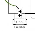
The snubber goes across the contacts or whatever is switching the load. For example the relays, switches, thyristors, triacs, contactors, and related products. :)

Ron
 

Tonyr1084

Joined Sep 24, 2015
9,744
@DS2068 Put snubbers on the Triac's the way shown in post 28. And include an additional resistor on the colored wires (my drawing) according to the parameters of the Triac's you purchase.

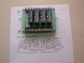
Here's a card with 4 triac's on it: https://www.amazon.com/Velleman-K26...8&qid=1504218293&sr=8-5&keywords=triac+switch

For less than $32 you're up and running on all 8 of your sprinklers. Beats the heck out of buying 8 SSR's at $10 a piece (or more).

[edit] Sorry, the seller says he has one in stock. Sorry, but that isn't enough. AND I didn't notice but this is a kit powered from a 9 volt battery. Still, if you can get the parts you should be able to duplicate the process. I also saw a listing for 1/2 pound of assorted Triac's. I don't know how many that would be but the cost was less than $4.00. There ARE options.
 
Last edited:
The snubber goes across the contacts or whatever is switching the load. For example the relays, switches, thyristors, triacs, contactors, and related products. :)

Ron
I realize this is an old thread, but this is not entirely correct.

When you turn off the power to a coil, it generates back emf (like an old automotive spark plug coil). This back emf can be 100,000s of volts and will propagate through a control system wiring causing operational faults and possibly damaging equipment. To prevent this from happening, a snubber is located as physically close to the coil as possible with the shortest possible wiring.

Putting a snubber around a switching element will protect the switching element itself from damage, but will not prevent the back emf from being generated and propagated through a control system.
 

MaxHeadRoom

Joined Jul 18, 2013
30,760
I realize this is an old thread, but this is not entirely correct.

When you turn off the power to a coil, it generates back emf (like an old automotive spark plug coil). This back emf can be 100,000s of volts and will propagate through a control system wiring causing operational faults and possibly damaging equipment. To prevent this from happening, a snubber is located as physically close to the coil as possible with the shortest possible wiring.
Putting a snubber around a switching element will protect the switching element itself from damage, but will not prevent the back emf from being generated and propagated through a control system.
I would refute that to a certain degree, if the snubber is efficient in preventing the high voltage spike there should be no further damage.
 
I would refute that to a certain degree, if the snubber is efficient in preventing the high voltage spike there should be no further damage.
I agree, if the coil is properly snubbed, the switch should not be exposed to noise spikes generated from the coil.

However I am willing to accept the value of protecting a solid state switch against spikes since you often are unable to get the snubber as close to the coil as it should be. Any excess wiring between the coil and the snubber reduce the effectiveness of the snubber (due to increased loop area). I have seen snubbers installed at a control panel that is quite a distance from the coil because that was the most practical method of installation even though this degrades the effectiveness of the snubber. Not optimal, but better than not at all.
 

crutschow

Joined Mar 14, 2008
38,624
I have seen snubbers installed at a control panel that is quite a distance from the coil because that was the most practical method of installation even though this degrades the effectiveness of the snubber.
Why do you say that?
Having the snubber at the panel means the snubber not only protects against the spike from the coil inductance, but also from the stray inductance of the wires from the panel to the coil.
 
Why do you say that?
Having the snubber at the panel means the snubber not only protects against the spike from the coil inductance, but also from the stray inductance of the wires from the panel to the coil.
It might help if I explain what back EMF means in this case. The key property of an inductor is you can't instantaneously change the current flowing through an inductor. When you open the switch, the magnetic fields collapsing in the coil generates a negative volt high enough to keep the current flowing for an instant longer. That is why switch/relay contacts arc when the switch is opened. If the contacts require 40,000 V to arc then that is what is present for a microsecond or so. That is exactly how the spark plug coil in a car turns 12VDC into 50,000V. That very short burst of current is made of very high frequencies signals. Impedance at high frequencies is more about geometry than anything else, which is why I mentioned loop area and why increasing loop area (making the wires to the snubber longer) makes things worse. High frequency currents flowing through wire is going to radiate EMI/RFI which couples easily to any wiring in the area. If you have any sensitive electronics connected it is possible they could be damaged by this.

When you add a snubber directly at the coil, there is a very little impedance between the coil and the snubber and the electrical disturbance is minimised. This is the same for a diode on DC and an RC snubber on AC power.

Putting the snubber across the switch does nothing to prevent the disturbance from happening, it just provides an alternative current path around the switch which prevents damage to the switch.
 

crutschow

Joined Mar 14, 2008
38,624
Putting the snubber across the switch does nothing to prevent the disturbance from happening,
I am perfectly aware of what generates the back EMF here (which is any inductance in the path from both the coil and the wire.
So It certainly does prevent the "disturbance".
The only difference is that prevents it at the contacts instead of directly at the coil, so any wire inductance does not create a spike.

And a properly designed snubber is designed to critically damp any oscillations to minimize EMI.
There is just a pulse of voltage when then decays to zero as the inductive energy is dissipated.
 
Top