Emmiter Follower Power Supply Getting Hot, Help!

Thread Starter

Timbob123

Joined Sep 30, 2019
31
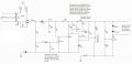
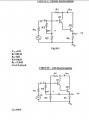
Hi, I have been trying for several weeks off and on to get my 100 VDC variable power supply to work with a 300ma inductive load. I have to be able to set it for 55V. When I do the output transistor gets hot (190F after 5 minutes). Its like the attached power supply circuit, but with a darlington set up (like attached). Ive tried switching to a mosfet, taking out the darlington set up (2 transistors). I still got hot. Not sure if a bootstrap capacitor (attached) would do anything, Im not switching or oscillating the input. The only thing that helped is paralleling the output transistors, but ended up with one getting hotter than the other, unless I had a separate drive transistor for each. Can anyone help with this? I don't want a ginormous heatsink. There must be something Im missing.
 

Attachments

AlbertHall

Joined Jun 4, 2014
12,338
With a 100V input and a 55V output there is 45V across the transistor and at 300mA that means there is 13.5W dissipation in that transistor (MOSFET or darlington makes no difference). That is going to need a substantial heat sink to keep the temperature down.

To use multiple transistors in parallel you should have a small resistor is each emitter connection to ensure that the transistors share the current equally.
 

crutschow

Joined Mar 14, 2008
34,201
There must be something Im missing.
Nope.
A linear regulator has to dissipate power equal to the input voltage minus the output voltage times the current, no matter what is used to reduce the voltage.
In your case that's (100V - 55V) * 0.3A = 13.5W.

The only way to reduce that dissipation is to use a switching regulator (SMPS).
 

DickCappels

Joined Aug 21, 2008
10,140
If you heart is set on using a linear power supply like an emitter or source follower, then make sure your transistor can handle the voltage and current you want and then make sure you provide adequate heatsinking. Linear regulators are often not as efficient as switching regulators but they usually generate a lot less noise.

The link below points to what looks like a good guide to finding the right heatsink for your application. If you still have questions, please aske them here.

https://www.designworldonline.com/how-to-select-a-suitable-heat-sink/
 

MisterBill2

Joined Jan 23, 2018
18,064
To reduce the heat in the control device in a linear voltage regulator you need to reduce the voltage drop across that device by lowering the input voltage. A much bigger heat sink will allow the heat to be removed, lowering the temperature, but it will not reduce the quantity of heat. So change the transformer voltage so that the regulator input is only 6 volts above the desired output and there will be much less heat generated.
 

MisterBill2

Joined Jan 23, 2018
18,064
You may want to evaluate the source of the 2n3055 transistors. Look at this .....
But Crutschow is correct, (100V - 55V) * 0.3A = 13.5W, and that 13.5 watts is heat.Only half as much heat as a small soldering iron, but those get quite hot, don't they. Dropping 45 volts in a transistor is going to get hot. The quality of the transistor does not matter except for how long it lasts. Heat is heat.
 

Thread Starter

Timbob123

Joined Sep 30, 2019
31
With a 100V input and a 55V output there is 45V across the transistor and at 300mA that means there is 13.5W dissipation in that transistor (MOSFET or darlington makes no difference). That is going to need a substantial heat sink to keep the temperature down.

To use multiple transistors in parallel you should have a small resistor is each emitter connection to ensure that the transistors share the current equally.
See the attached 90VDC Supply, I have the output transistors in parallel, emitter resistors, or base resistors?
 

Attachments

AlbertHall

Joined Jun 4, 2014
12,338
If you put a resistor in each emitter of the parallel transistors it will help to balance the current between them. The resistors should drop about 0.3V at the current which will be flowing in each transistor.
 

MisterBill2

Joined Jan 23, 2018
18,064
See the attached 90VDC Supply, I have the output transistors in parallel, emitter resistors, or base resistors?
The resistors to allow load sharing are in series in the emitter circuit. The function that they serve is to slightly reduce the base drive of each transistor in proportion to the emitter current. The resistors are usually 0.1 ohm, or less, for high power systems, but in this system with a lower load current I suggest using one ohm resistors. That will tend to equalize the heating of the transistors.
But to reduce the total power dissipated in the transistors you still need to decrease the input voltage to the rectifier. If you drop the 75 volts AC input to 50 volts that should give about 60 volts at the collectors of the pass transistors and reduce the heating to an acceptable value. There are simple ways to do that with standard transformers that are commonly available.
 

Thread Starter

Timbob123

Joined Sep 30, 2019
31
Thank you guys very much. I will try the resistors on each emitter leg tied together to the output. Because the TO-3 transistors are getting harder to find, do you think 2 Mosfets with resistors would do the same thing? I would eliminate my first transistor used in the Darlington.
 

Thread Starter

Timbob123

Joined Sep 30, 2019
31
In the attached circuit, there is a 2 transistor Darlington output (Q2 and the 2N6308). Can I drive both 2N6308 with Q2? Or will I need 2 Q2's? Then will I need the resistors?
 

Thread Starter

Timbob123

Joined Sep 30, 2019
31
There is more to the circuit than what is there, but Q5 is to open quickly when AC power is turned off, along with the suppression diodes.
Basically a fast decay of DC for the coil-load.
 

Thread Starter

Timbob123

Joined Sep 30, 2019
31
Here is the actual full circuit, attached. I have tried doubling output transistors (both of the Darlington set up- 4 transistors). I have also tried 2 Mosfets (R5- 100 ohm base emitter resistor removed and Q2 removed- base emitter jumped) with 1 ohm source (what would be emitter) resistors tied to output (temps were a little uneven 20F between), but this worked. If I can use the 2 fets I could use one heatsink, with fet on each side of the heatsink. I suppose I could also replace the other 2N6308 in the negative output lead with a fet, just don't know the resistor value changes to do that.
 

Attachments

Top