You guys are related to that youtube channel Primitive Technology? It seems.Instead of the cork and glass of water, I stuck the needle through a piece of rubber band and suspended the rubber band in the middle of the coil.
While most are nominally 10 MΩ, it isn't tightly controlled. The meter has an input impedance that comes out to be somewhere close to that and then it is calibrated to give the correct voltage reading, though I think they are usually pretty close (the manufacturer wants to do as little calibration as possible, after all).
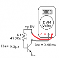
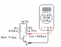
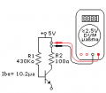
But look at the value of the base resistor you will need.If the measurement is 5 volts, the transistor is in saturation, if the transistor has a voltage less than five volts, We are in the linear region. If the voltage is zero volts, then the transistor is in cutoff. As to the base resistor, I can just audition several resistors until I find something in the range.
Amazon has LOTS of testers for transistors, but you do have to pay for themWhere did you get that?
My free Centech multimeters from Harbor Freight has one of those, as do some of the <U$10 multimeters from Amazon.One of my meters happened to have a transistor tester function with two 3 pin sockets, one for NPN and one for PNP.
I just bought 4 meters from Amazon for $4.97 each (to give to my Science Olympiad kids), It's a model XL830L, but the meter doesn't have a brand name on it (makes you wonder how little someone wants to be associated with it). They just arrived yesterday afternoon and so far I've only had the change to do a couple of simple tests of resistance and DC voltage, but they match within a couple LSDs of my Fluke 77 and 27. The have two 4-pin connectors for transistor checking (EBCE), making it easy to check any pin configuration except if the emitter is in the middle (don't think I've ever encountered that). So I decided to go ahead and test that feature using the same transistors I tested the h_FE on earlier in the thread. As near as I can tell, there's actually no socket there at all. The transistor pins feel like they are just going through the plastic holes in the case into open space. I thought maybe it was just the first meter I pulled out, so I tried it on a second and it was the same. So I pulled one of them apart and it is exactly what I expected -- there is no socket there at all. However, the board does have the 2x4 holes for a socket and so I put the 2n3904 into the holes and tilted it so that I had connection and it gave a forward h_FE of 248 and a reverse h_FE of 3, which is quite consistent with my earlier measurement, particularly since it's almost certainly using a different current that I did. This made me suspect that it's a case of the model I happened to buy not coming with that feature, but going back to the Amazon listing indicates that it does, as does the instruction manual that came with the meter. Fortunately, if I can scrounge up suitable header sockets, I can "repair" these brand-new meters.My free Centech multimeters from Harbor Freight has one of those, as do some of the <U$10 multimeters from Amazon.
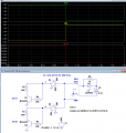
Several of my BC337 transistors have sufficient reverse gain to pass your test in both directions.The more basic test though is to just test to see if the transistor can work as a switch. I pointed this out in a previous post in this thread and had shown the two schematics for the two tests that need to be done. For the correct connection the transistor works well as a switch, for reversed connections it does not work at all.

What is the exact circuit you used, what measurements did you make, and what were the actual measurement results?Results were pretty disappointing, With very little difference between the proper orientation and the wrong one.
| Thread starter | Similar threads | Forum | Replies | Date |
|---|---|---|---|---|
|
|
Is it OK to Step down from 800V to 24V with Emitter Follower like this? | Power Electronics | 28 | |
| V | Low Pass filter and Open Collector Input | Homework Help | 12 | |
|
|
Spreadsheet for Common Emitter Amplifier Design (BJT) - Look what I did! | Analog & Mixed-Signal Design | 14 |