Emitter vs Collector.

Somewhere, I have an old BK transistor tester I picked up at a hamfest for a few dollars one year.

But yeah - I use one of those "part checkers" for when a part is super-unknown (ie - has a house number or no datasheet can be found).

I've found those super-handy when a part that looks like a resistor turns out to be an inductor (some people here have probably seen 'em - they have color band codes, look exactly like a thru-hole resistor - but the codes don't make sense, from a resistance perspective, and trying to measure them on a meter as a resistor also makes no sense).

I do have one "part" that I still have no idea how to measure - or really, to even know about maximum voltages, etc - it's a quadrant photo-diode (or photo-transistor - again, I can't find a datasheet for it), used to measure (supposedly, based on what I could find about similar parts) the position of a spot of light. It's mounted inside this metal, adjustable focus lens mount thing (I think it may have been for a very old photocopier). No idea beyond that how I could properly test it without potentially destroying it.

For now, it's one of many of my "curiosity parts"...
 

panic mode

Joined Oct 10, 2011
5,439
0.0048mA * 10000000 Ohm = 48000V

a bit high for typical BJT.

this should work with DMM on mA range, in which case red probe would need be on different DMM port
 

WBahn

Joined Mar 31, 2012
33,326
Most DVMs are 10MΩ input impedance. So this idea occurred to me.

While most are nominally 10 MΩ, it isn't tightly controlled. The meter has an input impedance that comes out to be somewhere close to that and then it is calibrated to give the correct voltage reading, though I think they are usually pretty close (the manufacturer wants to do as little calibration as possible, after all).

But your numbers are WAY off!

Just at first blush, if the gain of the transistor is ß, then the base resistor needs to be more than about ß·Rc to keep the transistor out of saturation.

With a 10 MΩ collector resistor and a 5 V supply, the absolute maximum collector current would be 0.5 µA (and that would put Vce at 0 V).

If you have 9.3 µA of base current, then the transistor will be in HARD saturation for any gain over 0.05. Even in reverse active operation, most BJTs have a current gain of at least unity, usually 3 to 10 and sometimes quite a bit more (I measured a gain of 50 just this week).
 

Thread Starter

Wendy

Joined Mar 24, 2008
23,869
If the measurement is 5 volts, the transistor is in saturation, if the transistor has a voltage less than five volts, We are in the linear region. If the voltage is zero volts, then the transistor is in cutoff. As to the base resistor, I can just audition several resistors until I find something in the range. I have a large number of resistors I can use for the audition. If the transistor is in the linear region, that is the sweet spot.
 

WBahn

Joined Mar 31, 2012
33,326
If the measurement is 5 volts, the transistor is in saturation, if the transistor has a voltage less than five volts, We are in the linear region. If the voltage is zero volts, then the transistor is in cutoff. As to the base resistor, I can just audition several resistors until I find something in the range.
But look at the value of the base resistor you will need.

In the forward active region with a typical small signal transistor that can have current gains of well over 200, any base resistor less than about 1.7 GΩ will put it into saturation. How many 1+ GΩ transistors do you have?

Even with a transistor with a reverse active gain of only 5, your base resistor would need to be over 50 MΩ. And if it saturations both ways, you'll have to go higher.

What is the point of wanting to use your meter's input resistance? Does it really save you that much effort compared to just putting it across 10 kΩ collector resistor and using a 1 MΩ base resistor?
 

MrAl

Joined Jun 17, 2014
13,870
Where did you get that?
Amazon has LOTS of testers for transistors, but you do have to pay for them :)
For example, $20 USD will get you a tester probably not too bad for that price. Going higher in price probably gets you more options.

One of my meters happened to have a transistor tester function with two 3 pin sockets, one for NPN and one for PNP. I never wanted that but I liked the meter so I purchased it anyway. It was around $100 USD and I bought it probably 30 years ago (maybe around 1996 or something).

If you do buy a tester, make sure it does not use over 5v for the tests for bipolar transistors. The gain can drop significantly if the emitter base is reversed biased by a voltage that is higher than the rating. The gain then drops significantly and is almost no use in high frequency circuits. I think it messes up what we sometimes call the "emitter efficiency".

The more basic test though is to just test to see if the transistor can work as a switch. I pointed this out in a previous post in this thread and had shown the two schematics for the two tests that need to be done. For the correct connection the transistor works well as a switch, for reversed connections it does not work at all.
 

Thread Starter

Wendy

Joined Mar 24, 2008
23,869
Okay, scrap, my previous idea is a brain fart. I'll post another idea shortly. One of the things I love about electronics is I can do home experiments very cheaply and easily, even in my diminished state.
 

WBahn

Joined Mar 31, 2012
33,326
My free Centech multimeters from Harbor Freight has one of those, as do some of the <U$10 multimeters from Amazon.
I just bought 4 meters from Amazon for $4.97 each (to give to my Science Olympiad kids), It's a model XL830L, but the meter doesn't have a brand name on it (makes you wonder how little someone wants to be associated with it). They just arrived yesterday afternoon and so far I've only had the change to do a couple of simple tests of resistance and DC voltage, but they match within a couple LSDs of my Fluke 77 and 27. The have two 4-pin connectors for transistor checking (EBCE), making it easy to check any pin configuration except if the emitter is in the middle (don't think I've ever encountered that). So I decided to go ahead and test that feature using the same transistors I tested the h_FE on earlier in the thread. As near as I can tell, there's actually no socket there at all. The transistor pins feel like they are just going through the plastic holes in the case into open space. I thought maybe it was just the first meter I pulled out, so I tried it on a second and it was the same. So I pulled one of them apart and it is exactly what I expected -- there is no socket there at all. However, the board does have the 2x4 holes for a socket and so I put the 2n3904 into the holes and tilted it so that I had connection and it gave a forward h_FE of 248 and a reverse h_FE of 3, which is quite consistent with my earlier measurement, particularly since it's almost certainly using a different current that I did. This made me suspect that it's a case of the model I happened to buy not coming with that feature, but going back to the Amazon listing indicates that it does, as does the instruction manual that came with the meter. Fortunately, if I can scrounge up suitable header sockets, I can "repair" these brand-new meters.
 

WBahn

Joined Mar 31, 2012
33,326
The more basic test though is to just test to see if the transistor can work as a switch. I pointed this out in a previous post in this thread and had shown the two schematics for the two tests that need to be done. For the correct connection the transistor works well as a switch, for reversed connections it does not work at all.
Several of my BC337 transistors have sufficient reverse gain to pass your test in both directions.
 

Thread Starter

Wendy

Joined Mar 24, 2008
23,869
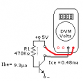
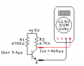
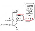
I had to shake some serious rust off of my dead brain cells to come up with this. This looks like a more approachable result. ß is assumed to be fifty.

E vs C.png​

It might even be useful to measure beta, with a slight rearrangement.
 
Last edited:

crutschow

Joined Mar 14, 2008
38,932
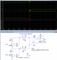
Here's the LTspice sim of a simple circuit that determines whether a transistors pins are CBE or EBC for either an NPN or PNP transistor:
The LED lights when the pin order is CBE top to bottom in the schematic.

Two transistor orientations are shown for the simulation, switched by S1 and S2 to show the forward and reverse connection results.
The real circuit will have no S1, S2, or CKT 2, which are just for the simulation.

The real DPDT toggle switch SW1 changes polarity for NPN and PNP transistors.
The switch can also determine whether the transistor is NPN or PNP as the LED will not light with either orientation for the opposite polarity transistor.

R5 shunts the small current generated by the base current and the low transistor Beta in the reverse connection, so the LED won't light dimly under that condition.

The sim is configured for the NPN connection, showing that the LED (red trace) is only on with the correct CBE polarity (Q1 powered, green trace).

1791132678380.png
 
Last edited:

Thread Starter

Wendy

Joined Mar 24, 2008
23,869
Results were pretty disappointing, With very little difference between the proper orientation and the wrong one.
 

WBahn

Joined Mar 31, 2012
33,326
Results were pretty disappointing, With very little difference between the proper orientation and the wrong one.
What is the exact circuit you used, what measurements did you make, and what were the actual measurement results?

Maybe we can explain why your results were not definitive. It's likely a matter of just using different component values, but maybe your circuit had issues as well.
 

kiroma

Joined Apr 30, 2014
308
One thing no one mentioned is the Early effect. @Wendy , you could measure IC (collector current) at 2 different VCE, and the change between currents is due to the Early effect. So you can narrow it down to what current is due to Early and what current is due to amplification.
That won't tell you about which terminal is which, but it's one step further measuring a more exact hFE.
Because at sufficiently high voltages (VCE) with sufficiently low currents (IB), one might confuse the current due to Early effect with the amplified current, leading to a very distorted hFE from reality.
This is just a note that can happen to confuse someone, but generally it won't matter outside these conditions.
 
Top