Facebook
 Google
 GitHub
 Linkedin

Design a + 10V regulated supply for load currents from 0 to 100 mA using a zener and an emitter follower; the input voltage is +20 to +25 V.
Allow at least 10 mA zener current under all (worst-case) conditions. What power rating must the zener have?
EDIT:
What are the differences (pros and cons) between the circuit with the emitter follower and the one with zener and resistor only (attached) ?
Calculate worst-case dissipation in transistor and zener
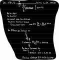
I implemented the solution with resistor and zener diode (see attached photo),
But it is not very clear to me how to accomplish it with a follower emitter:
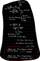
I understood that it has a high input impedance and this allows reducing any loss from a generic Thevenin circuit at the input ... and I also understood that the output on the emitter follows the input on the base with a voltage gain of 1.
What I do not understand is:
1) how come the current gain is high? is it mathematically proven from the small signal model ?
2) Some help on how to solve the exercise
Here are some of my thoughts on the exercise:
(a) while in the exercise with diode and resistor the 10mA of the Zener guaranteed 10V on it (and thus on Vo because Vo=Vz), I guess it is the same here. With Vz=10V the output is Vz-Vbe=9.3V --> I have to guarantee Vz=10.7V
b) the bjt is in the active zone (?) since it is not a switching application
Allow at least 10 mA zener current under all (worst-case) conditions. What power rating must the zener have?
EDIT:
What are the differences (pros and cons) between the circuit with the emitter follower and the one with zener and resistor only (attached) ?
Calculate worst-case dissipation in transistor and zener
I implemented the solution with resistor and zener diode (see attached photo),
But it is not very clear to me how to accomplish it with a follower emitter:
I understood that it has a high input impedance and this allows reducing any loss from a generic Thevenin circuit at the input ... and I also understood that the output on the emitter follows the input on the base with a voltage gain of 1.
What I do not understand is:
1) how come the current gain is high? is it mathematically proven from the small signal model ?
2) Some help on how to solve the exercise
Here are some of my thoughts on the exercise:
(a) while in the exercise with diode and resistor the 10mA of the Zener guaranteed 10V on it (and thus on Vo because Vo=Vz), I guess it is the same here. With Vz=10V the output is Vz-Vbe=9.3V --> I have to guarantee Vz=10.7V
b) the bjt is in the active zone (?) since it is not a switching application
Attachments
-
 206.2 KB Views: 3
Last edited: