Facebook
 Google
 GitHub
 Linkedin
Hi everybody!
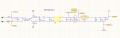
For nearly a year I have designed a prototype touch switch for household use.
I tested with the household electrical device in my lab, It works very well, including resistive loads (such as drilling), led driver...
But, when I installed at some of my friend's apartments, it couldn't work. Touch operation is unstable, there is interference.
I was using commom choke mode filter in AC input...
I can't find the cause.
I hope to receive support from the community.
Thank you in advance!