EMF - Problem

Thread Starter

swmitchell

Joined Nov 14, 2013
18
Hi everyone, if ya can spend a sec... I need some advice. I have a really noisy motor and I'm having some troubles suppressing it's EMF (I think).

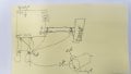
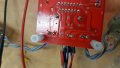
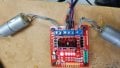
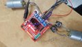
SO I'm after some general advice for cleaning up 5us +- 1v noise. I've put a whole bunch of .1 uf caps all over the place - IE across the motor terminal, between each terminal and the jacket of the motor (Big improvement there)... across the output of the linear regulator across the power in of my Processor (arduino uno). Just .1 uf SMD on the underside of the GND and +5v.

the thing is If I scope out the 5v on the chip I still see power ripples on the chip. (I solder a little wire to the underside of the GND and the 2 5v pins)
the ripple is 5.6v... obviously it hangs...

Any Suggestions on how I can suppress this more. Should I be using perhaps a bigger cap... (it's a pretty fine signal...)... the motor's are .1uf THC... and were else I can I use SMD's.

It feels like some how the wires from the motors are acting like a transmitter and the power wire (or the legs of the chip itself) is acting like a receiver... is that even possible, the wires do run parallel?... again... I'm not after a magic bullet, but some general advice.

If ya know a good book, or online resource I'm happy to go there, but a quick google only gives me captian obvious advice (flybackdiodes and power filters).

Cheers!
 

Janis59

Joined Aug 21, 2017
1,894
1) Most widespread reason for "EMF-noisy motor" ir simply weak accumulator coming to the end of life. Check it by the fresh, probably problem will sef-cure.
2) Some rare cases the reason is diy HV wiring to spark plugs. It must be used wires with large resistance. If that are ordinary wires, then problem is there.
3) Last is the defect in antenna cable (coaxial) braiding earthening. Probably lost contact.
 

MrSoftware

Joined Oct 29, 2013
2,273
Can you show your schematic? Is the motor powered by your linear regulator, or separately? Try adding a larger cap to the input and possibly the output of your linear regulator, maybe 10 or 20uF. Also try some other size capacitors, IN ADDITION TO your 0.1uF on the processor. Different sizes have the most effect at different frequencies, so by adding multiple sizes in parallel you will more effectively filter a wider range of frequencies. Maybe add a 1uF and 10uF as close as you can physically get them to your processor pins.

Also if you have a choice, run your higher current wires as far away from your signal wires as you physically can. Wires do act like antennas, and running wires parallel to each other will definitely make them more susceptible to picking up noise from each other.

Edit --> Search youtube for bypass capacitor info by EEVBlog, great info in those videos.
 

Thread Starter

swmitchell

Joined Nov 14, 2013
18
These are all great suggestions... (the diode one is so obvious!) but I reckon separating the wire bundle out could help... and the multiple cap idea is a good one also...

I'll begin some serious tinkering and share my findings.

I have attached 2 super high quality "cad" files to show my physical layout (ish) and the placement of the .1uf caps. (more to show respect of request than expectations).

Really, all the tips are great! Thanks. (anyone wanna see the robot I'm working on once it's going?
 

Attachments

MisterBill2

Joined Jan 23, 2018
27,501
Running a brush type motor on the same power supply as a device that is sensitive to high noise levels will never work. And mostly the problem is not "emf", but rather the commutation noise (EMI), as the segments enter and leave contact with the brushes. To reduce the electrical noise radiated by the wires, the two motor power wires should be twisted together. Twisting tends to mostly cancel both magnetic radiation and electrostatic radiation by cancelling the fields. If you can possibly use separate voltage sources for the processor and the motor that can help more than anything else.
 

Thread Starter

swmitchell

Joined Nov 14, 2013
18
ok ok. I admit I need some help now.
I have
Shortened the wires, and simplified to the motor controller and the motors.
Here are 3 pickies.
img 3 - shows .1uf cap across the terminals of both motors and a 10 uf cap across the 5v out (in the middle).
img 4 - shows the motors (with wires twisted and shortned and a .1uf cap across the terminals of the motors.
img 5 shows (apologies for the rotation)... the power spike (and time scale)
to trigger this I bridge ground to the init pins... this is all out of the robot now, I think I damaged my processor.. :(

Big thanks to all... Each Suggestion has made it 'better' but... I admit, this problem has me... flummoxed.

There is no inductor in series on the motors (as you can see), but I'd have to order in.

What would happen if I earthed the shield of the motor?...
Any suggestions? I'm kinda stuck for ideas. (a different motor perhaps)... I'm totally open for wisdom and guidance.
 

Attachments

Thread Starter

swmitchell

Joined Nov 14, 2013
18
Running a brush type motor on the same power supply as a device that is sensitive to high noise levels will never work. And mostly the problem is not "emf", but rather the commutation noise (EMI), as the segments enter and leave contact with the brushes. To reduce the electrical noise radiated by the wires, the two motor power wires should be twisted together. Twisting tends to mostly cancel both magnetic radiation and electrostatic radiation by cancelling the fields. If you can possibly use separate voltage sources for the processor and the motor that can help more than anything else.
sorry... I read this after my past post... going to try now.
 

Thread Starter

swmitchell

Joined Nov 14, 2013
18
ahah! I think I found the source... the old simplify simplify simplify!...

I scoped out the motors. Check this out.
They are giving between 20-40V EMF.
For the fist time I have a precise questions that relates exactly to this... should I change the motors? Will I EVER beable to filter out this?!
 

Attachments

Thread Starter

swmitchell

Joined Nov 14, 2013
18
I was skeptical about the inductors... but check this out...

image 8 - the left motor running (with 2 big beefy inductors on the lead) - 'what is this?' no power spike....
image 9 - the the setup...
image 99 0 the right motor (no inductors)... still that nasty power EMF!

So there I have it.... general motor EMF problem solving.

1 - add a few isolating caps close to the source and the sensitive parts.
2 - separate the power from the data.
3 - add series inductor on the motor.

I'm thinking this is actually setting up some kind of low pass filter between the caps and the inductance... (I'm probably overdoing it on the inductors ATM... but it's what I have on hand.)

I'm wondering if I can just wrap the motor wire a few times around a ferrite core... more to come as I do a bit more experimenting, and have a few more parts.

Please chime in with your thoughts, I'm taking this as a learning project now...
 

Attachments

MisterBill2

Joined Jan 23, 2018
27,501
Series inductors and shunt capacitors ARE a low-pass filter, and it looks like perhaps an adequate one for this application. Quite probably grounding the motor case will provide additional reduction in the remaining noise, but you may need to try a few different "ground" points. Over the years I have reduced the noise to an OK level in a lot of installations, and the best point for tying the shield to ground is not always obvious at the start.
If you are able to locate those chokes close to the motor terminals it will reduce the amount of noise that can radiate from the motor connection wires. And if you can use 2-conductor shielded cable for the motor power that should help even more. Foor this application it looks like success is in sight!
 

MrSoftware

Joined Oct 29, 2013
2,273
Great job so far. I could not tell where you put the 1uF and 10uF caps in relation to your processor, but they should be as close as is physically possible. As in solder them directly to the leads on your processor package if possible. Killing the noise at the source is never a bad thing, but making the rest of the system more noise tolerant means adding filter caps as close as is possible to the components that are affected by the noise. And as mentioned above, separate the power supplies if at all possible. Also bring all your grounds together at a single point if you can.
 

Thread Starter

swmitchell

Joined Nov 14, 2013
18
Great job so far. I could not tell where you put the 1uF and 10uF caps in relation to your processor, but they should be as close as is physically possible. As in solder them directly to the leads on your processor package if possible. Killing the noise at the source is never a bad thing, but making the rest of the system more noise tolerant means adding filter caps as close as is possible to the components that are affected by the noise. And as mentioned above, separate the power supplies if at all possible. Also bring all your grounds together at a single point if you can.
I didn't show the .1uf cap on my processor and a 10uf cap on the power in on the board.... but I soldered the SMD straight onto the PCB, between the 5v and GND pins... I didn't show this because after I started simplifying the problem it became clear I was looking in the wrong place for the solution. Great suggestion (thanks).
 
Top